12Lf-xxPT-40 Datasheet
1. Features
- Micro size
- Precise position control
- Stall Force control by current feedback
- Speed control (1024 resolution)
- Strong force comparing to the size
- Built-in Drive Circuitry
- TTL/PWM communication
- Parameter programmable on the Manager software
2. Specification
2.1 Common Specifications
Property | Value |
|---|---|
Stroke | 40mm |
Rated Load | 10N ~ 78N |
Recommended duty cycle at rated load | 50% |
Max apllicable Load | 2times rated load |
Recommended duty cycle at max applicable load | under 20% (20%) |
Micro controller | 32bit Arm Cortex |
Position Resolution | 4096 Resolution (A/D Converter) |
Input Voltage | 12.0V(Rated), 7.4V ~ 13 V(Operating) |
Motor Type / Watt | Coreless DC Motor / 3.5 Watt |
Current consumption | 30mA(Idle), 380mA(Rated), 1.6A(Stall) |
Position repeatability | Unidirectional less than 0.03mm(30um) |
Bydirectional less than +/0.06mm(60um) | |
Current Tolerance | ±15% at Over 50mA |
Position sensor | 10kΩ linearity potentiometer |
Size, Weight | 86.9(L)x36(W)x18(H)mm /96~99g (to be varied according to gear ratio) |
Communication | TTL/PWM(Automatic signal recognition) |
Protocol | IR Robot Open Protocol (switchable to MODBUS RTU protocol) |
Operating Temperatures | -10℃ ~ 60℃ |
Ingress protection | IP-54 |
Mechanical Backlash | 0.03mm(30um) |
Audible Noise | Max. 50db at 1m |
Gear ratio | 10:1(10PT,17PT,27PT) /20:1(42PT) 30:1(55PT) /50:1(78PT) |
Gear type | Engineering plastic gears(10PT,17PT,27PT) 4metal & 2engineering plastic gears(42PT,55PT,78PT) (Aluminum and stainless steel combination) |
Rod type | Stainless steel rod |
Standard Accessory | 1xHinge base |
Connector Type (Male) in the Actuator | MOLEX 22-03-5035 |
Wire Harness | Molex(50-37-5033) to Molex(50-37-5033)/ 200mm / 0.08x60(22AWG) |
2.2 Volatges
| Parameter | Min | Norm | Max | Unit | Note |
|---|---|---|---|---|---|
| Supply voltage | 7.4 | 12 | 13 | V | |
| Logic input voltage | 2.0 | 3.3 | 5.5 | V | TTL |
2.3 Currents
| Parameter | Min | Norm | Max | Unit | Note |
|---|---|---|---|---|---|
| Maximum peak Current | ≤1.6 | A | Stall Current | ||
| No Load Current | ≤300 | mA | No Load | ||
| Rated Load Current | ≤400 | mA | 800mA or higher setting | ||
| Max Applicable Load Current | ≤600 | mA | 1.6A setting | ||
| Idle Current | ≤35 | mA |
2.4 Temperatures
| Parameter | Min | Norm | Max | Unit | Note |
|---|---|---|---|---|---|
| StorageTemp. | -20 | - | 70 | ℃ | |
| Operating Temp. | -10 | - | 60 | ℃ |
2.5 Strokes
| Parameter | Min | Norm | Max | Unit | Note |
|---|---|---|---|---|---|
| MIN Position | 3.2 | 3.7 | 4.2 | mm | ⁕ |
| MAX Position | 43.2 | 43.7 | 44.2 | mm | |
| Stroke length | 40.0 | mm |
- Contact us if min position of multiple actuators should be exactly same.
- Synchronize Min / Max Position by “Min / Max Position Calibration” feature on Manager software or Parameter Map
2.6 PWM
Parameter | Min | Norm | Max | Unit | Note |
|---|---|---|---|---|---|
MIN Pulse | 900 | us | Period is 8ms over | ||
Neutral Pulse | 1500 | us | |||
MAX Pulse | 2100 | us |
2.7 No Load Speed
Parameter | Min | Norm | Max | Unit | Note |
|---|---|---|---|---|---|
Maximum Speed at 12.0V | 104.4 | 116.0 | 127.6 | mm/s | 12Lf-10x-40 |
45.6 | 84.0 | 92.4 | mm/s | 12Lf-17x-40 | |
26.1 | 29.0 | 31.9 | mm/s | 12Lf-27x-40 | |
13.95 | 15.5 | 17.05 | mm/s | 12Lf-42x-40 | |
9.27 | 10.3 | 11.33 | mm/s | 12Lf-55x-40 | |
6.93 | 7.7 | 8.47 | mm/s | 12Lf-78x-40 |
2.8 Load
Parameter | Min | Rated | Max | Unit | Note |
|---|---|---|---|---|---|
Load at 12.0V | 10.0 | 20.0 | N | 12Lf-10x-40 | |
2.24 | 4.49 | lbf | |||
1.01 | 2.03 | kgf | |||
17 | 34 | N | 12Lf-17x-40 | ||
3.82 | 7.64 | lbf | |||
1.73 | 3.47 | kgf | |||
27 | 54 | N | 12Lf-27x-40 | ||
6.07 | 12.13 | lbf | |||
2.76 | 5.51 | kgf | |||
42 | 84 | N | 12Lf-42x-40 | ||
9.44 | 18.87 | lbf | |||
4.29 | 8.57 | kgf | |||
55.0 | 110.0 | N | 12Lf-55x-40 | ||
12.36 | 24.72 | lbf | |||
5.60 | 11.20 | kgf | |||
78 | 156 | N | 12Lf-78x-40 | ||
17.53 | 35.05 | lbf | |||
7.96 | 15.91 | kgf |
⁕ 1 kgf = 9.8N, 1lbf = 4.45N
Caution
Use under rated load conditions as much as possible. When applying the maximum applicable load (2 times the rated load), set Goal current to 1600(1.6A) and reduce Duty cycle to 20% or less.
2.9 Self Lock Feature
Parameter | Min | Norm | Max | Unit | Note |
|---|---|---|---|---|---|
Slef Lock | - | N/A | - | 12Lf-10x-40 | |
- | - | 12Lf-17x-40 | |||
- | Available | - | 12Lf-27x-40 | ||
- | - | 12Lf-42x-40 | |||
- | - | 12Lf-55x-40 | |||
- | - | 12Lf-78x-40 |
Tip
Self-Lock means the actuator can hold its position by mechanical friction alone, without motor power.
3. Reference Data
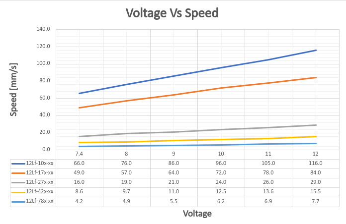
3.1 Voltage Vs Speed
Graph showing speed change at no load according to input voltage. This data includes error and is for reference only.
Note
Voltage Vs Speed data was tested at Goal Current 800. This data includes about +/-15% error.
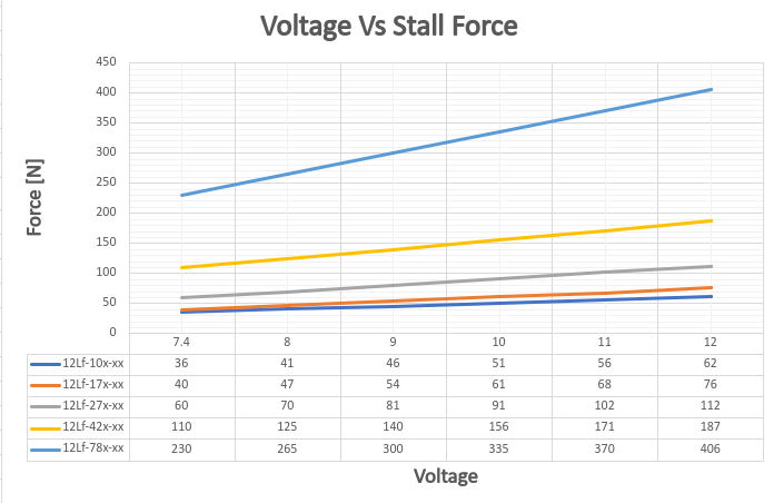
3.2 Voltage Vs Stall Force
Stall Force measured at 800mA according to input voltage. This data includes error and is for reference only.
Note
Voltage Vs Stall Force data was tested at Goal Current 1600. Each force value has an error of +/- 15%.
Caution
Stall force is for reference only. To prevent product damage, use within rated load in actual applications.
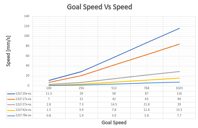
3.3 Goal Speed Vs Speed
Shows no load speed change according to Goal Speed Parameter value when Goal Current is 800. Under rated load, the time to reach maximum speed varies depending on the load.
Note
Goal Speed Vs Speed data was tested at Goal Current 800.
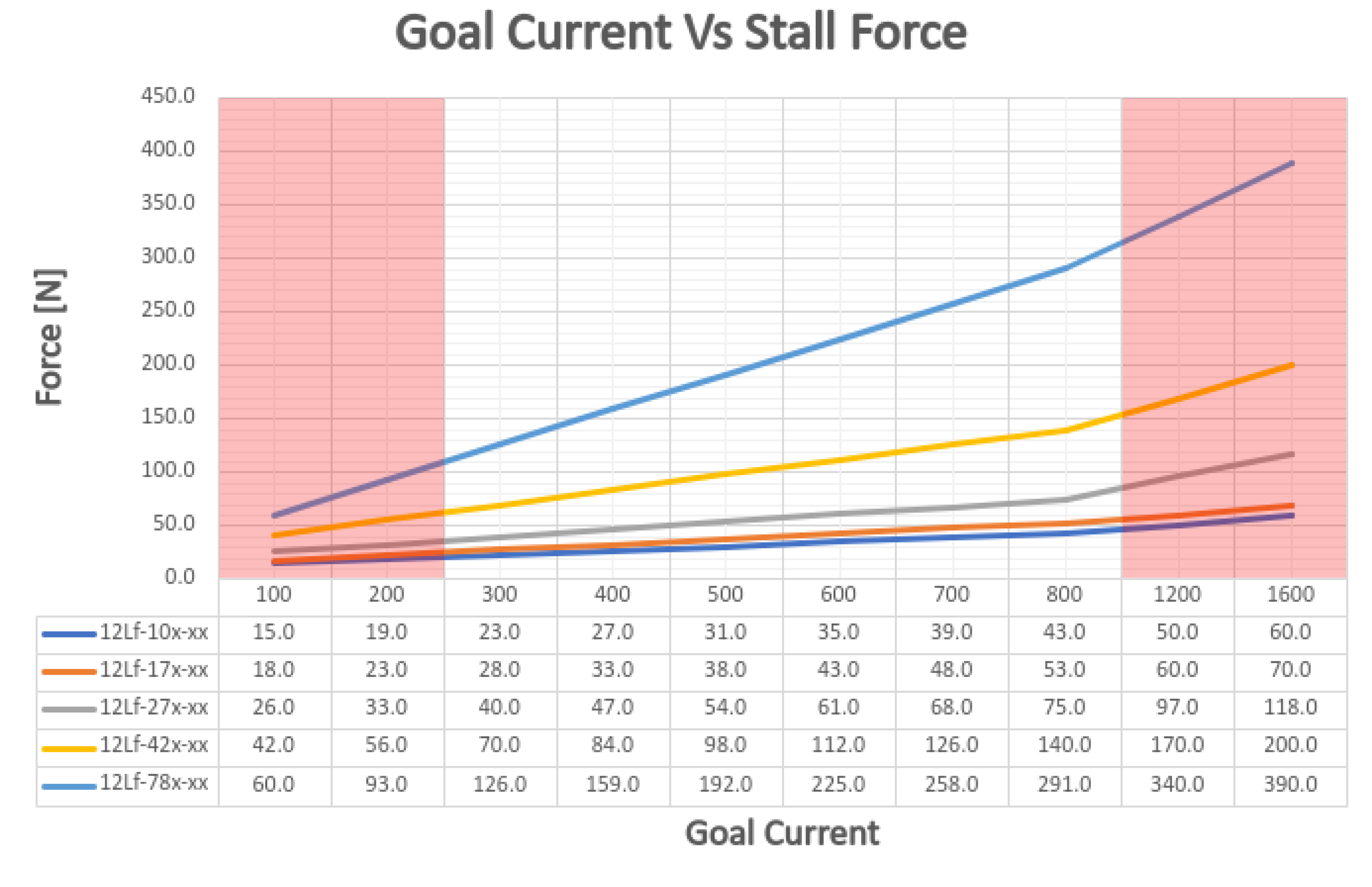
3.4 Goal Current vs Stall Force
Shows mightyZAP's Stall Force for each Goal Current value. Stall Force was measured at minimum speed to reflect only the force from current.
TIP
This data shows the motor's force. It is recommended to set Goal current to 3 times the actual load. If the difference between actual load and motor force is small, speed decreases. If equal, the motor does not move.
Caution
Each Stall Force value has an error of +/- 15%. Red-marked areas have large error due to internal load and heat, so use for reference only. If continuous load causes current over 1A, the current value gradually drops and stabilizes at 1A.
Double load setting
mightyZAP can be used up to double load. For double load, set Duty Rate to 20% or less. **ex>
Load Goal Current Duty rate Load Goal Current Duty Rate 20N(Rated) 800 Max. 50% 35N(Rated) 800 Max. 50% 40N(Max) 1600 Max. 20% 70N(Max) 1600 Max. 20%
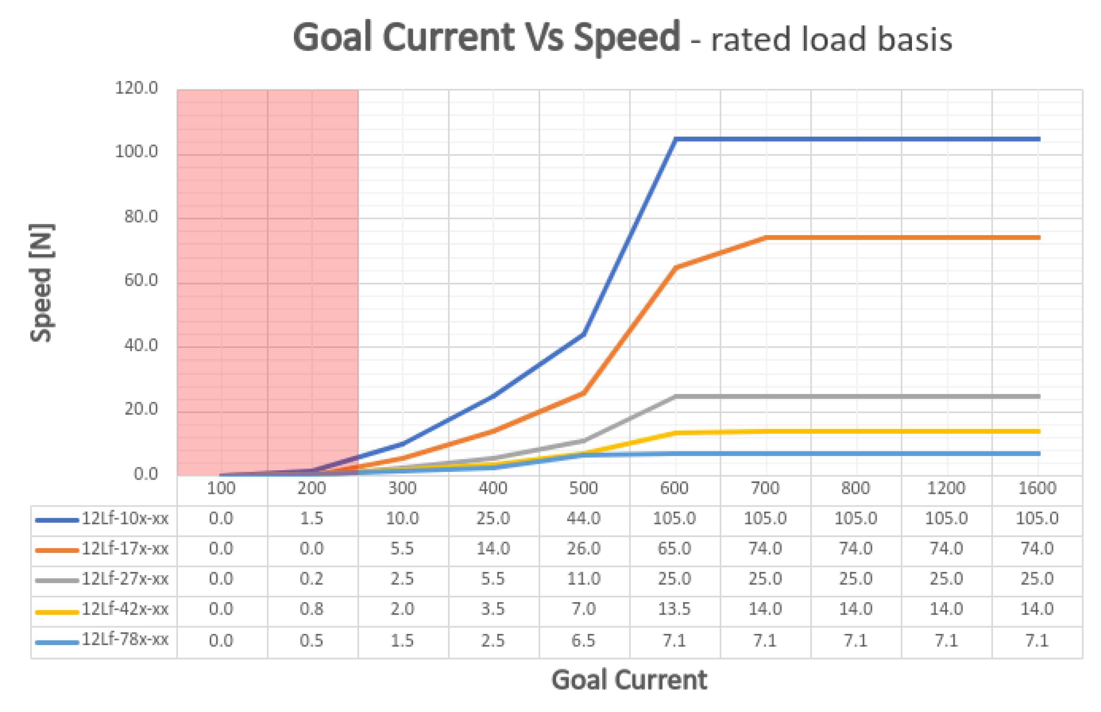
3.5 Goal Current vs Speed at Rated Load
Shows mightyZAP's speed change for each Goal Current value at rated load.
TIP
Goal Current Vs Speed data was measured at rated load.
Caution
Speed data has about +/-10% error. Red-marked areas are where Stall Force and rated load are similar, so mightyZAP may not move. Use for reference only.
3.6 PIN Map
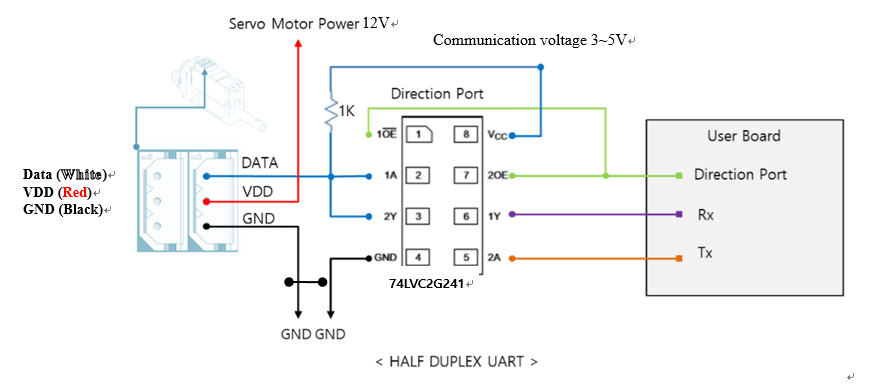
| PIN NUMBER(COLOR) | PIN NAME | FUNCTION |
|---|---|---|
| 1(WHITE) | DATA | Communication |
| 2(RED) | VCC | Power + |
| 3(BLACK) | GND | Power - |