L12-xxPT-6 Datasheet
1. Features
- Micro size
- Precise position control
- Strong force comparing to the size
- Built-in Drive Circuitry
- TTL/PWM communication
- Parameter programmable on the Manager software
2. Specification
2.1 Common Specifications
| Property | Value |
|---|---|
| Stroke | 56mm |
| Rated Load | 17N~78N according to gear ratio(See appendix.) |
| Recommended duty cycle | under 50% |
| Micro controller | 32bit Arm Cortex |
| Position Resolution | 4096 Resolution (A/D Converter) |
| Input Voltage | 12.0V(Rated), 7.4V ~ 13 V(Operating) |
| Motor Type / Watt | Coreless DC Motor / 3.5 Watt |
| Current consumption | 30mA(Idle), 380mA(Rated), 1.6A(Stall) |
| Position repeatability | Unidirectional less than 0.04mm(40um) |
| Bydirectional less than +/0.08mm(80um) | |
| Position sensor | 10kΩ linearity potentiometer |
| Size, Weight | 111.5(L)x36(W)x18(H)mm /124~127g (to be varied according to gear ratio) gear ratio) |
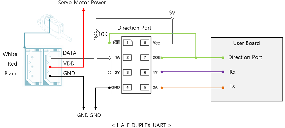
| Communication | TTL/PWM(Automatic signal recognition) → TTL Level voltage : 3.3 ~ 5.0V → PWM Pulse range : 900us(retracted) – 1500us(center) – 2100us(extended) → TTL Communication range : Max.4m |
| Protocol | IR Open Protocol (MODBUS is for Force control lineup only.) |
| Operating Temperatures | -10℃ ~ 60℃ |
| Ingress protection | IP-54 |
| Mechanical Backlash | 0.03mm(30um) |
| Audible Noise | Max. 50db at 1m |
| Gear ratio | 10:1(20PT,30PT) 20:1(50PT) /50:1(80PT) |
| Gear type | Engineering plastic gears(20PT,30PT) 4metal & 2engineering plastic gears(50PT,80PT)(Aluminum and stainless steel combination) |
| Rod type | stainless steel |
| Standard Accessory | 1xHinge base 1x Hinge 1xHinge shaft 1xRod end tip 2x M3 NUT 3 x M2.5x6 screws 1x Molex wire harness (200mm) 1 x M3 spanner 1 x Socket set screwlex wire harness (200mm) 1 x M3 spanner 1 x Socket set screw |
| Connector Type (Male) in the Actuator | MOLEX 22-03-5035 |
| Wire Harness | Molex(50-37-5033) to Molex(50-37-5033)/ 200mm / 0.08x60(22AWG) |
2.2 Volatges
| Parameter | Min | Norm | Max | Unit | Note |
|---|---|---|---|---|---|
| Supply voltage | 7.4 | 12 | 13 | V | |
| Logic input voltage | 2.0 | 3.3 | 5.5 | V | TTL |
2.3 Currents
| Parameter | Min | Norm | Max | Unit | Note |
|---|---|---|---|---|---|
| Maximum peak Current | 2.1 | 2.2 | 2.3 | A | Stall Current |
| No Load Current | 180 | 200 | 220 | mA | No Load |
| Rated Load Current | 420 | 450 | 480 | mA | Rated Load |
| Idle Current | 25 | 30 | 35 | mA |
2.4 Temperatures
| Parameter | Min | Norm | Max | Unit | Note |
|---|---|---|---|---|---|
| StorageTemp. | -20 | - | 70 | ℃ | |
| Operating Temp. | -10 | - | 60 | ℃ |
2.5 Strokes
| Parameter | Min | Norm | Max | Unit | Note |
|---|---|---|---|---|---|
| MIN Position | 2.6 | 3.1 | 3.6 | mm | |
| MAX Position | 58.1 | 58.6 | 59.1 | mm | |
| Stroke length | 55.5 | mm |
⁕ Synchronize Min / Max Position by “Min / Max Position Calibration” feature on Manager software or Parameter Map.
2.6 PWM Signal
| Parameter | Min | Norm | Max | Unit | Note |
|---|---|---|---|---|---|
| Min Pulse | 900 | us | Period 8~21ms | ||
| Neutral Pulse | 1500 | us | |||
| Max Pulse | 2100 | us |
2.7 No Load Speed
| Parameter | Min | Norm | Max | Unit | Note |
|---|---|---|---|---|---|
| Maximum Speed at 12.0V | 72 | 80 | 88 | mm/s | L12-20PT-x |
| 25.2 | 28 | 30.8 | mm/s | L12-30PT-x | |
| 9.45 | 10.5 | 11.55 | mm/s | L12-50PT-x | |
| 6.93 | 7.7 | 8.45 | mm/s | L12-80PT-x |
2.8 Load
| Parameter Parameter | Min | Rated | Max | Unit | Note |
|---|---|---|---|---|---|
| Load at 12.0V | 17.0 | N | L12-20PT-x | ||
| 3.82 | lbf | ||||
| 1.73 | kgf | ||||
| 31.0 | N | L12-30PT-x | |||
| 6.96 | lbf | ||||
| 3.16 | kgf | ||||
| 50.0 | N | L12-50PT-x | |||
| 11.24 | lbf | ||||
| 5.09 | kgf | ||||
| 78 | N | L12-80PT-x | |||
| 17.53 | lbf | ||||
| 7.95 | kgf |
⁕ 1 kgf = 9.8N, 1lbf = 4.45N
2.9 Self Lock Feature
| Parameter | Min | Norm | Max | Unit | Note |
|---|---|---|---|---|---|
| Slef Lock | - | N/A | - | L12-20x-x | |
| - | Available | - | L12-30x-x | ||
| - | - | L12-50x-x | |||
| - | - | L12-80x-3 |
Tip
Self-lock feature :The force which actuator maintains its position by mechanical friction without motor power.
3. Reference
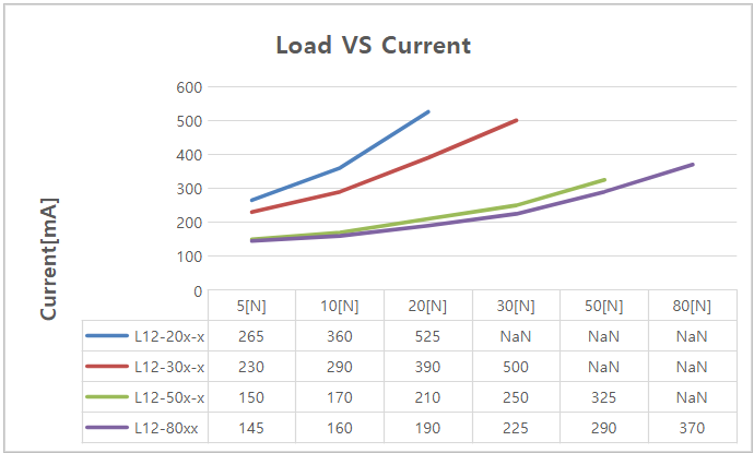
3.1 Load Vs Current
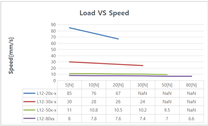
3.2 Load Vs Speed
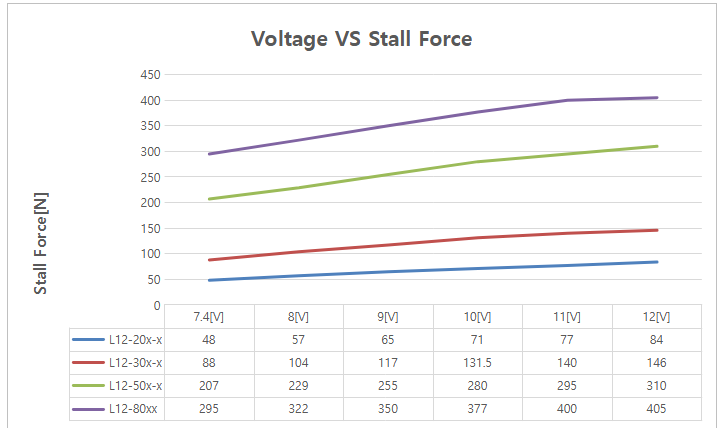
3.3 Voltage Vs Stall Force
3.4 Voltage Vs Speed

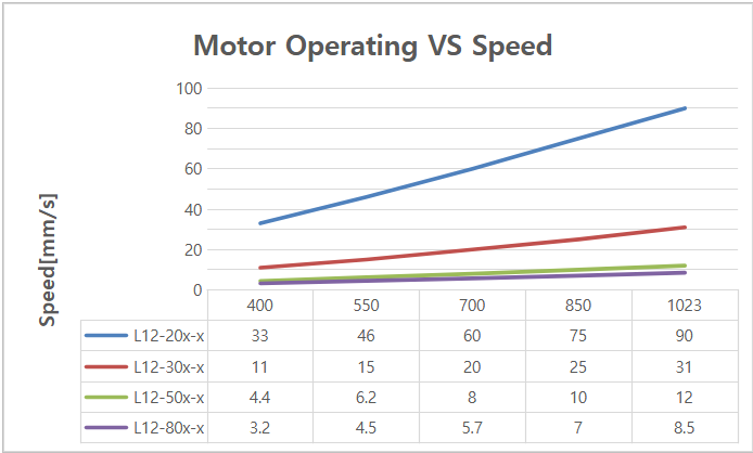
3.5 Motor Operating Rate
3.6 PIN Map
| PIN NUMBER(COLOR) | PIN NAME | FUNCTION |
|---|---|---|
| 1(WHITE) | DATA | |
| 2(RED) | VCC | |
| 3(BLACK) | GND |