L12-xxF-4 Datasheet
1. Features
- Micro size
- Precise position control
- Strong force comparing to the size
- Built-in Drive Circuitry
- RS-485 communication
- Parameter programmable on the Manager software
2. Specification
2.1 Common Specifications
| Property | Value |
|---|---|
| Stroke | 40mm |
| Rated Load | 17N~78N according to gear ratio(See appendix.) |
| Recommended duty cycle | under 50% |
| Micro controller | 32bit Arm Cortex |
| Position Resolution | 4096 Resolution (A/D Converter) |
| Input Voltage | 12.0V(Rated), 7.4V ~ 13 V(Operating) |
| Motor Type / Watt | Coreless DC Motor / 3.5 Watt |
| Current consumption | 30mA(Idle), 380mA(Rated), 1.6A(Stall) |
| Position repeatability | Unidirectional less than 0.03mm(30um) |
| Bydirectional less than +/0.06mm(60um) | |
| Position sensor | 10kΩ linearity potentiometer |
| Size, Weight | 86.9(L)x36(W)x18(H)mm **/**96~99g (to be varied according to gear ratio) |
| Communication | RS-485 |
| Protocol | IR Open Protocol (MODBUS is for Force control lineup only.) |
| Operating Temperatures | -10℃ ~ 60℃ |
| Ingress protection | IP-54 |
| Mechanical Backlash | 0.03mm(30um) |
| Audible Noise | Max. 50db at 1m |
| Gear ratio | 10:1(20PT,30PT) 20:1(50PT) /50:1(80PT) |
| Gear type | Engineering plastic gears(20PT,30PT) 4metal & 2engineering plastic gears(50PT,80PT)(Aluminum and stainless steel combination) |
| Rod type | stainless steel |
| Standard Accessory | 1xHinge base 1x Hinge 1xHinge shaft 1xRod end tip 2x M3 NUT 3 x M2.5x6 screws 1x Molex wire harness (200mm) 1 x M3 spanner 1 x Socket set screwlex wire harness (200mm) 1 x M3 spanner 1 x Socket set screw |
| Connector Type (Male) in the Actuator | MOLEX 22-03-5035 |
| Wire Harness | Molex(50-37-5033) to Molex(50-37-5033)/ 200mm / 0.08x60(22AWG) |
2.2 Volatges
| Parameter | Min | Norm | Max | Unit | Note |
|---|---|---|---|---|---|
| Supply voltage | 7.4 | 12 | 13 | V | |
| Logic input voltage | 2.0 | 3.3 | 5.5 | V | TTL |
2.3 Currents
| Parameter | Min | Norm | Max | Unit | Note |
|---|---|---|---|---|---|
| Maximum peak Current | 2.1 | 2.2 | 2.3 | A | Stall Current |
| No Load Current | 180 | 200 | 220 | mA | No Load |
| Rated Load Current | 420 | 450 | 480 | mA | Rated Load |
| Idle Current | 25 | 30 | 35 | mA |
2.4 Temperatures
| Parameter | Min | Norm | Max | Unit | Note |
|---|---|---|---|---|---|
| StorageTemp. | -20 | - | 70 | ℃ | |
| Operating Temp. | -10 | - | 60 | ℃ |
2.5 Strokes
| Parameter | Min | Norm | Max | Unit | Note |
|---|---|---|---|---|---|
| MIN Position | 3.2 | 3.7 | 4.2 | mm | |
| MAX Position | 43.2 | 43.7 | 44.2 | mm | |
| Stroke length | 40.0 | mm |
⁕ Synchronize Min / Max Position by “Min / Max Position Calibration” feature on Manager software or Parameter Map.
2.6 No Load Speed
| Parameter | Min | Norm | Max | Unit | Note |
|---|---|---|---|---|---|
| Maximum Speed at 12.0V | 72 | 80 | 88 | mm/s | L12-20PT-x |
| 25.2 | 28 | 30.8 | mm/s | L12-30PT-x | |
| 9.45 | 10.5 | 11.55 | mm/s | L12-50PT-x | |
| 6.93 | 7.7 | 8.45 | mm/s | L12-80PT-x |
2.7 Load
| Parameter Parameter | Min | Rated | Max | Unit | Note |
|---|---|---|---|---|---|
| Load at 12.0V | 17.0 | N | L12-20PT-x | ||
| 3.82 | lbf | ||||
| 1.73 | kgf | ||||
| 31.0 | N | L12-30PT-x | |||
| 6.96 | lbf | ||||
| 3.16 | kgf | ||||
| 50.0 | N | L12-50PT-x | |||
| 11.24 | lbf | ||||
| 5.09 | kgf | ||||
| 78 | N | L12-80PT-x | |||
| 17.53 | lbf | ||||
| 7.95 | kgf |
⁕ 1 kgf = 9.8N, 1lbf = 4.45N
2.8 Self Lock Feature
| Parameter | Min | Norm | Max | Unit | Note |
|---|---|---|---|---|---|
| Slef Lock | - | N/A | - | L12-20x-x | |
| - | Available | - | L12-30x-x | ||
| - | - | L12-50x-x | |||
| - | - | L12-80x-3 |
Tip
Self-lock feature :The force which actuator maintains its position by mechanical friction without motor power.
3. Reference
3.1 Load Vs Current
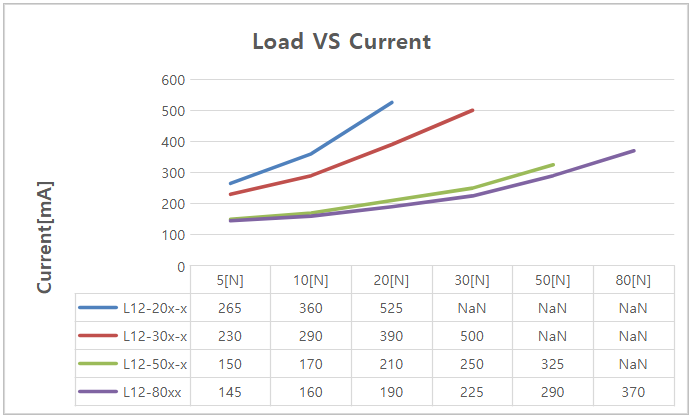
※ Data includes tolerance.
3.2 Load Vs Speed
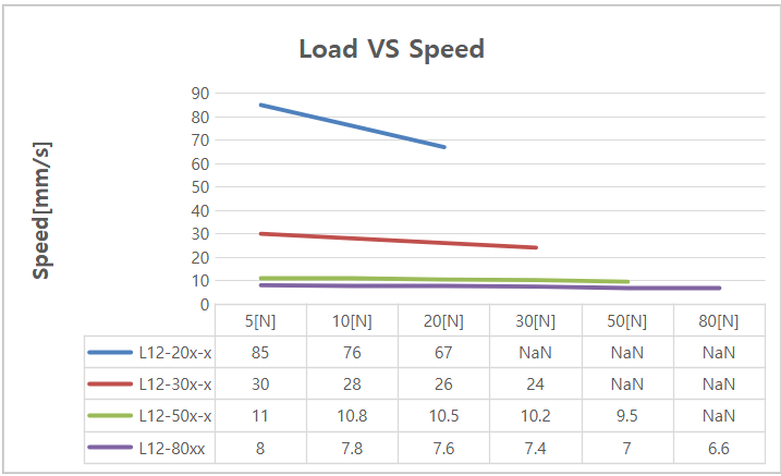 ※ Data includes tolerance.
3.3 Voltage Vs Stall Force
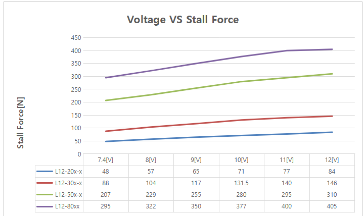 ※ Data includes tolerance.
3.4 Voltage Vs Speed
 ※ Data includes tolerance.
3.5 Motor Operating Rate
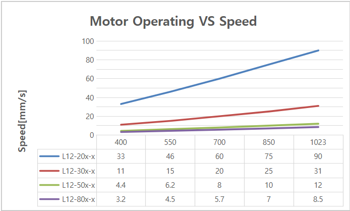 ※ Data includes tolerance.
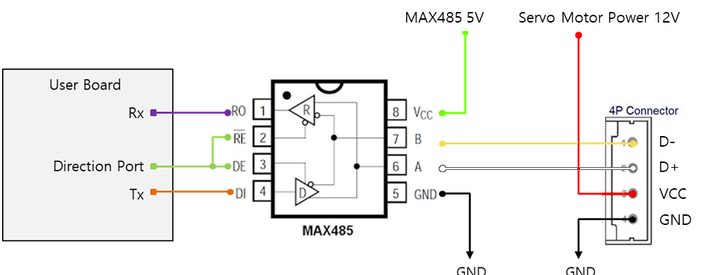
3.6 PIN Map
| PIN NUMBER(COLOR) | PIN NAME | FUNCTION |
|---|---|---|
| 1(YELLOW) | D- | RS 485 - |
| 2(WHITE) | D+ | RS 485 + |
| 3(RED) | VCC | Power + |
| 3(BLACK) | GND | Power - |