IR-USB03 Datasheet
| SERIES | VOLTAGE |
|---|---|
| 17Lf / 12Lf / 12Df / D12 / L12 | 12V input |
| D7 Series | 7.4V input |
| 17Bb Series | 24V input |
(USB to Half Duplex TTL / RS485 Converter)
Introduction
- The IR-USB03 is an USB to RS485 (or TTL) converter board that connects the actuator and PC to use the PC software mightyZAP manager.
- It is a replacement model with the same function as the old IR-USB02, but the USB port has been changed to Type-C and a termination resistor and dedicated case have been added.
- The input power of the actuator must be separately applied through the power terminal of IR-USB03 according to the purchased actuator input voltage. Both Half Duplex TTL or RS-485 communications are available.
- After connecting the PC and the actuator through IR-USB03, user can intuitively perform various parameter settings, data monitoring, motion tests, and firmware updates through the PC software mightyZAP Total Manager.
1. Features
- Product Category : USB to Half Duplex TTL/RS485 Converter
- Compatible System : PC (Windows, Mac OS, Linux)
- Baudrate : 9600 ~ 115200 bps
- Host port : USB Type-C
- Device port : Half Duplex TTL, RS485
- TTL, RS485 Voltage Level : 3.3V
- Power Input Voltage : DC 7V⁓25V (Typical : 12V)
- Current Capacity : 4A (Max)
- Over Current Protection : 5.2A (Based on a temperature of 20°C)
- Power Input ESD Protection : ±30KV
- RS485, TTL ESD Protection : ±15KV
- Built-in RS485 Terminating Resistor(120ohm)
- Storage temperature : -40°C ~ 105°C
- Operating temperature : -40°C ~ 85°C
- Size / Weight : 56.4 * 54 * 16 (mm) / 29g
2. Composition
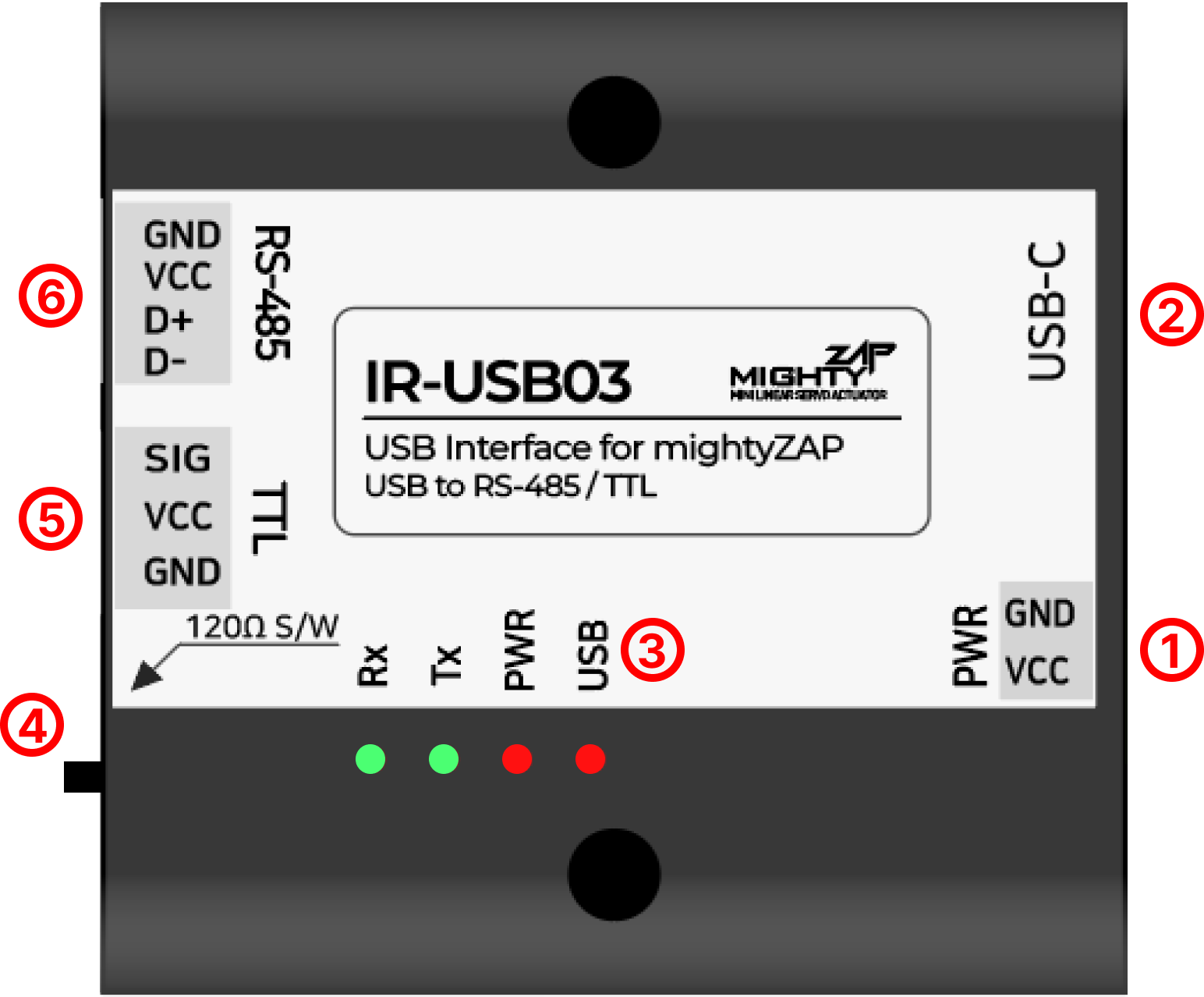
1) Power Input Port
- Power supply port for actuator power and internal circuit operation (7.4V, 12V, 24V supply depending on actuator specifications)
**WARNING!**
- Make sure to apply proper rated voltage to your mightyZAP actuator to prevent serious damage. (7.4V or 12V or 24V)
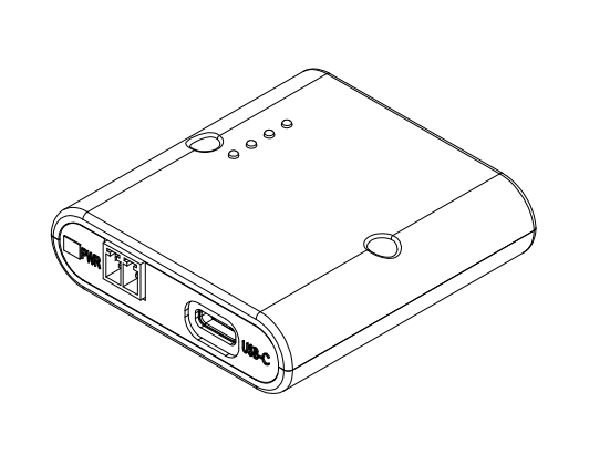
2) USB Type-C Port
- USB Type C port for Communication
(Do not use “charging only” cable, but use communication capable cable.)
3) LED Indicators
- USB : USB Port input status
- PWR : Power Input status
- TX : Communication TX data status
- RX : Communication RX data status
4) RS-485 Terminating Resistor Switch
- Termination resistance 120Ω ON/OFF switch (Default OFF)
5) TTL Port
- Half duplex TTL communication port for actuator
6) RS-485 Port
- RS-485 communication port for actuator
3. Pin Map
1) Power Input Port
| PIN NUMBER | PIN NAME | FUNCTION |
|---|---|---|
| 1 | VCC | Power Input |
| 2 | GND | GND |
**CAUTION!**
• Do not use batteries as a power source for the IR-USB03. This may cause product malfunction & serious damage. • To prevent damage to the product, pay attention to the power polarity when supplying the power and supply appropriate voltage for the actuator specifications.
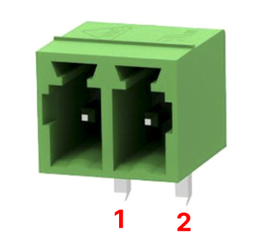
2) TTL Port
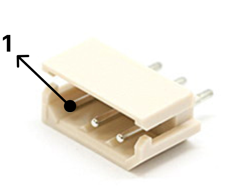
| PIN NUMBER | PIN NAME | FUNCTION |
|---|---|---|
| 1(WHITE) | SIG | TTL Data |
| 2(RED) | VCC | Power Output (Supply to Actuator) |
| 3(BLACK) | GND | GND |
3) RS-485 Port
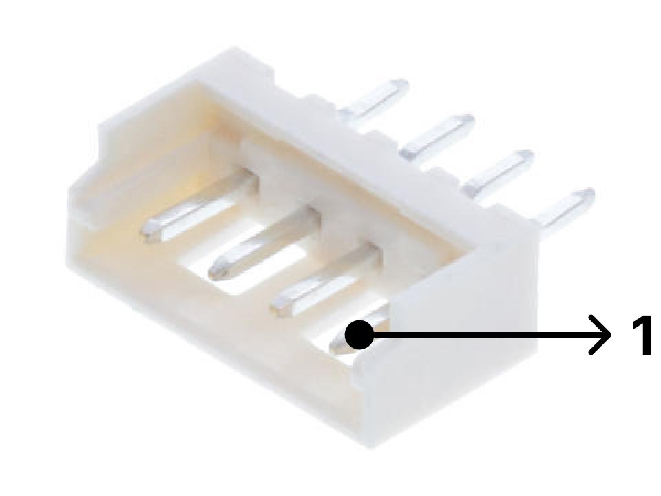
| PIN NUMBER | PIN NAME | FUNCTION |
|---|---|---|
| 1(YELLOW) | D- | RS-485 - |
| 2(WHITE) | D+ | RS-485 + |
| 3(RED) | VCC | Power Output ( Supply to Actuator ) |
| 4(BLACK) | GND | GND |
CAUTION!
• Be careful of miswiring and short circuits to prevent damage of the board or actuator. We recommend using a genuine wire harness or bulk connectors from us.
4. ELECTRICAL CHARACTERISTICS
| Parameter | Symbol | Values | Unit | Remarks | ||
|---|---|---|---|---|---|---|
| Min | Typ | Max | ||||
| Power Input Voltage | VIN | 7.0 | 12.0 | 27.0 | V | Supply proper input voltage for each actuator’s spec. |
| Idle Current | VIN | ≤ 10 | mA | |||
| Communication Current | VIN | ≤ 100 | mA | |||
| Current Capacity | VIN | 3.0 | 4.0 | A | ||
| Over Current Protection | VIN | 4.7 | 5.2 | 5.7 | Ambient Temperature 0°C → 5.7A 35°C → 4.7A | |
| Communication Voltage Level | SIG, D+, D- | -3.3 | 3.3 | V | TTL, RS485 | |
CAUTION!
• The rated input voltage of the L12, D12, 12Lf, and 17Lf series is 12V. Actuator may damage if voltage over 13V is applied.
5. Configuration Settings
5.1 USB Driver installation & Port connection
5.1.1 Windows
Step 1. USB Dirver (CP 210x VCP Driver) Download The IR-USB03’s Driver will be installed automatically by Windows Update. If it is not installed automatically, please download the driver through the link below.
Download the CP210x Universal Windows Driver from the link below and unzip it. https://www.silabs.com/developers/usb-to-uart-bridge-vcp-drivers?tab=downloads
Step 2. Port connection & Driver installation Right-click the “silabser.inf” file in the unzipped folder and select Install. 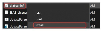
When you click the Install button, a warning message will appear as shown right. Then, click the OPEN button and proceed with the installation. 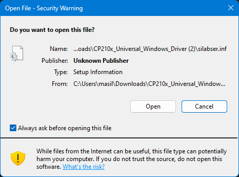
Once the installation is complete, a pop-up window like the one below will appear. 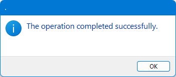
Connect IR-USB03 to the PC. Check if the Serial Port is connected normally in [System]-[Device Manager]-[Port]. If it is connected normally, you can see that a new com port is added as shown in the image below. 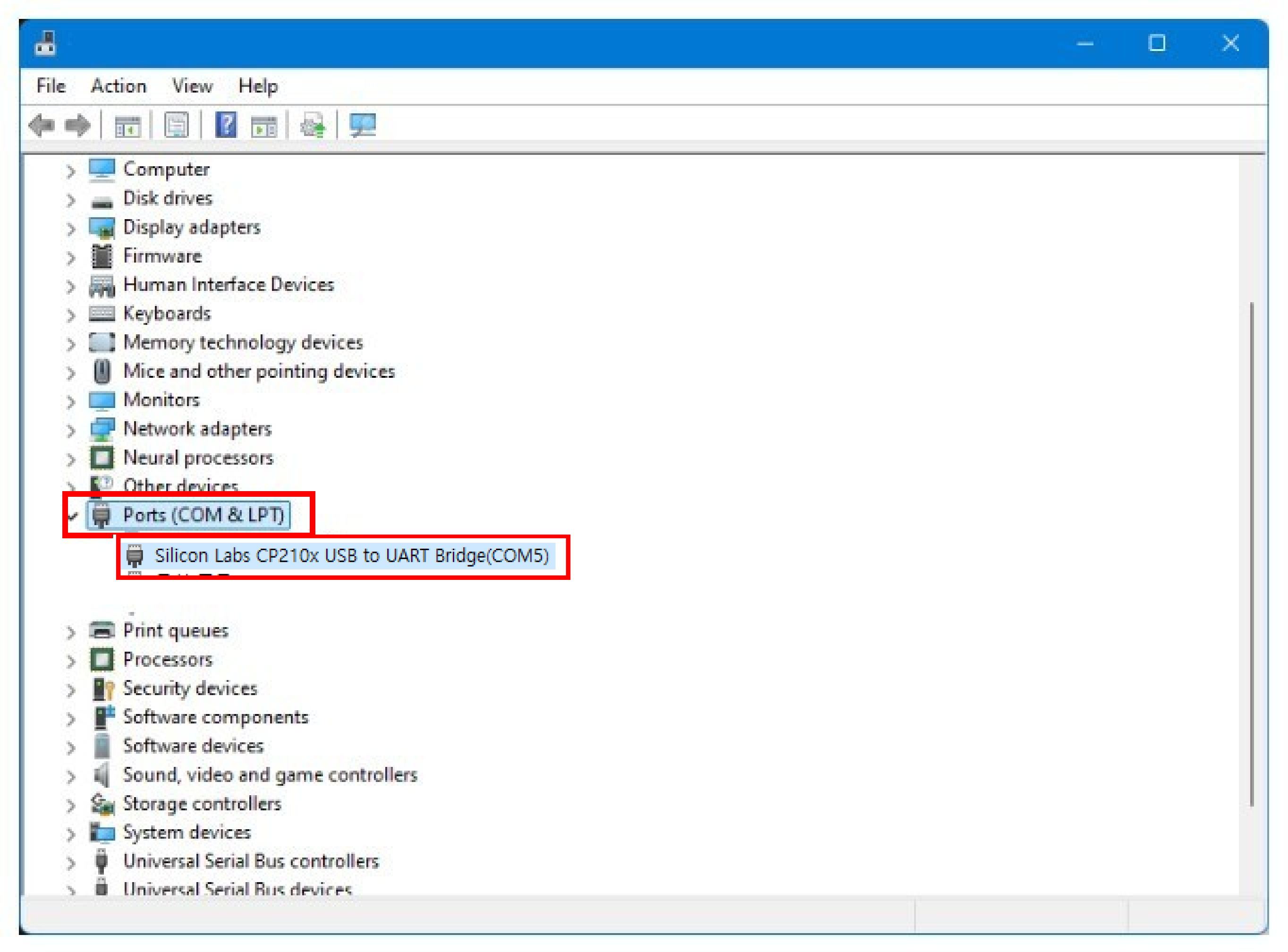
5.1.2 Linux[Ubuntu/Demian]
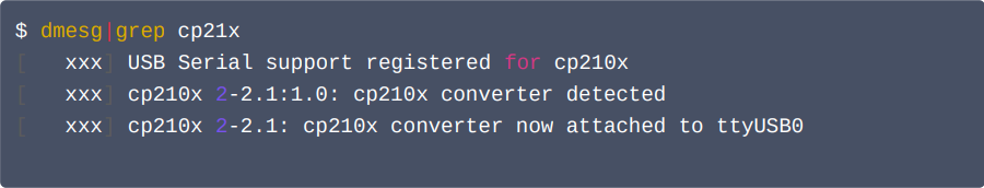
Step 1. Check Comport The CP210x driver has been distributed as part of the Linux kernel since v2.6.12. On Linux, the CP210x driver appears as /dev/ttyUSBx. How to check COM port:
- Connect the USB Interface board to the PC with an appropriate USB cable. (Not charging only cable)
- Open terminal window and type below, then will see below output :
Step 2. Obtaining Serial Port Permissions Ubuntu basically requires users to log in as a regular user, not as a root user, so user needs to set permissions to handle system devices such as the Serial Port. First, enter the command below to check the connected port name. 
Check the usage group using the serial port identified through the “ls -l” command. 
Use the “id Gn” command to check which group the currently logged in user belongs to. 
Since the currently logged-in user is not included in the dialout group, add the dialout group to the current user. 
After adding to a group, user must log out and log in again for the changes to take effect.
5.1.3 Mac OS
The driver installation instructions are based on Mac OS X10.15 and macOS 11/12. For earlier OS X versions, please refer to FTDI's "Mac OS X Installation Guide" published before 2017.
Download the VCP Driver from the link below. https://www.silabs.com/developers/usb-to-uart-bridge-vcp-drivers?tab=downloads
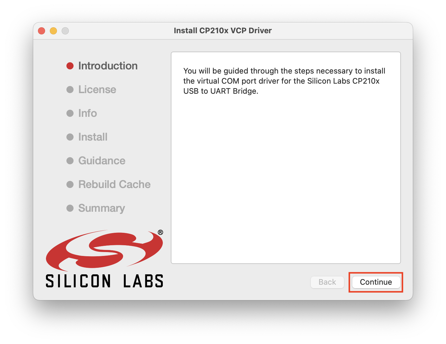
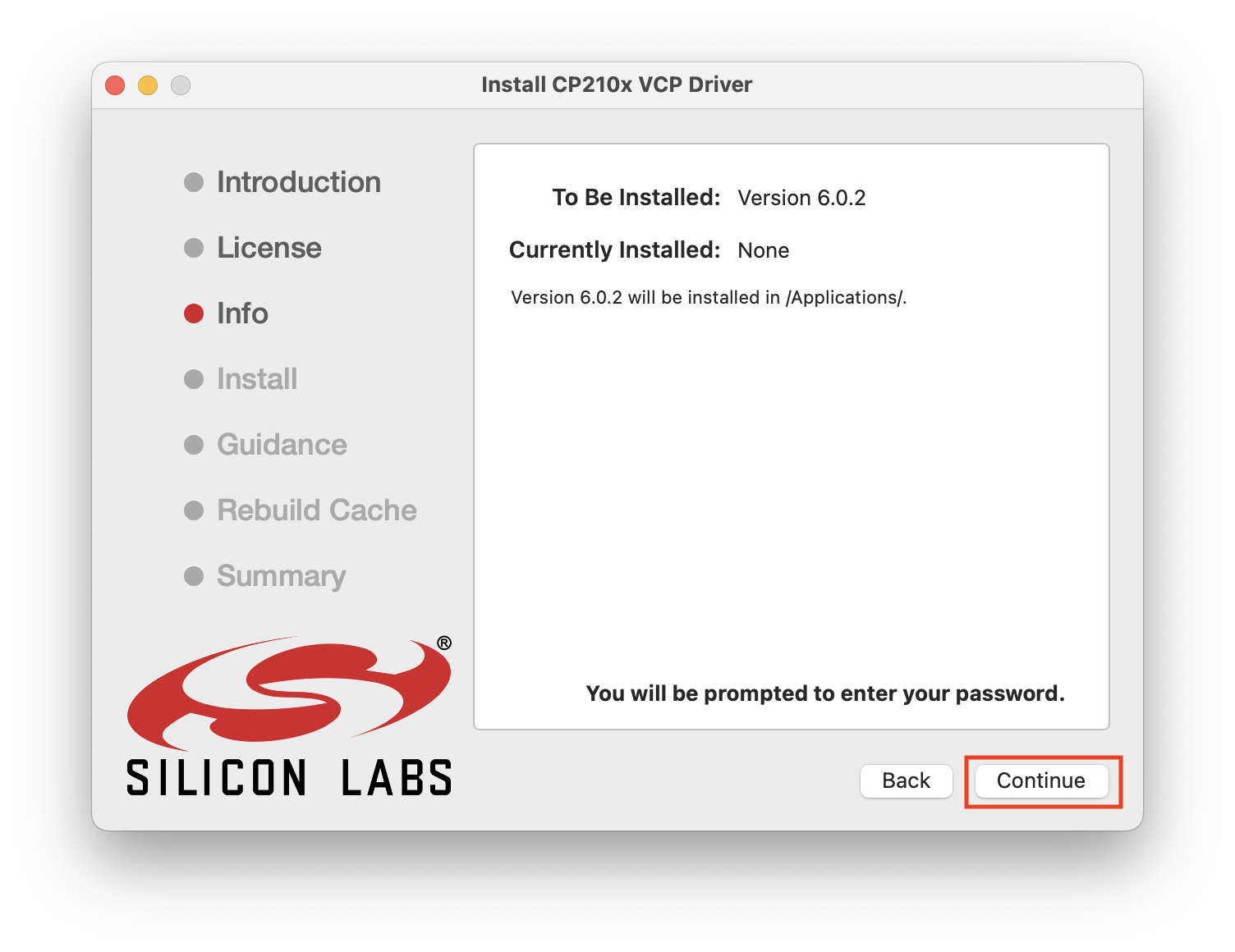
Step1. Installation in Application folder Run the downloaded “Install CP210x VCP Driver” file. 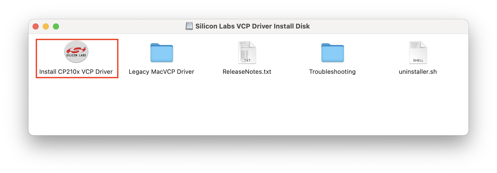
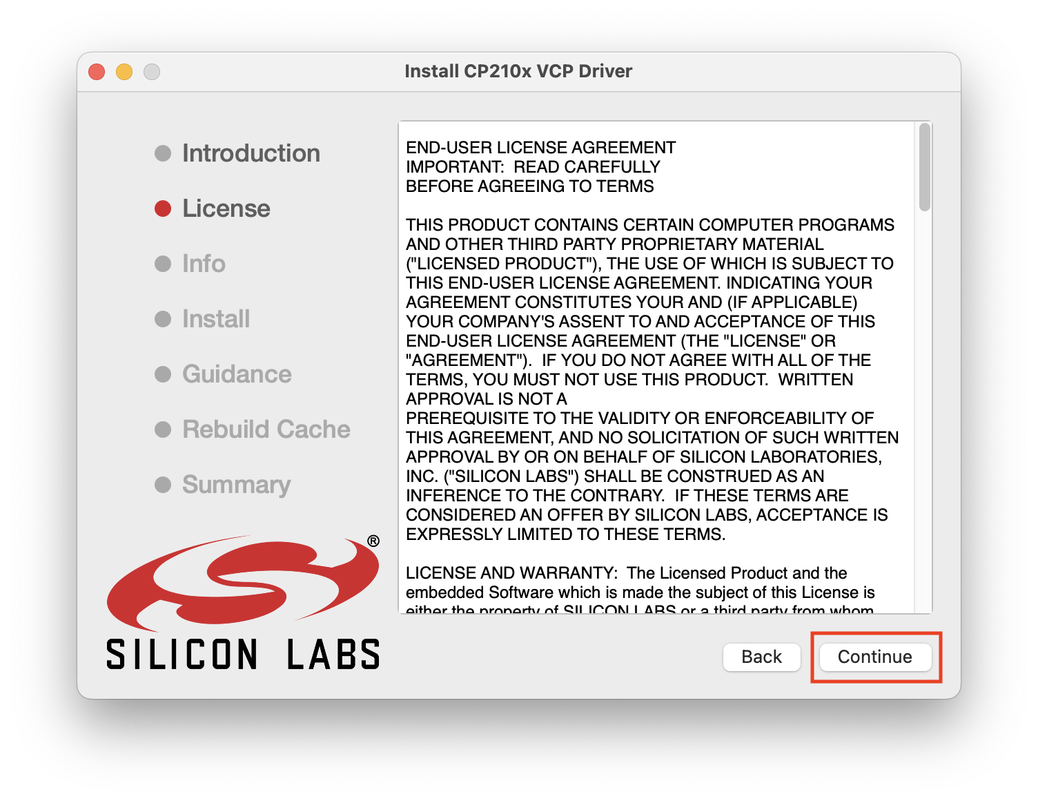
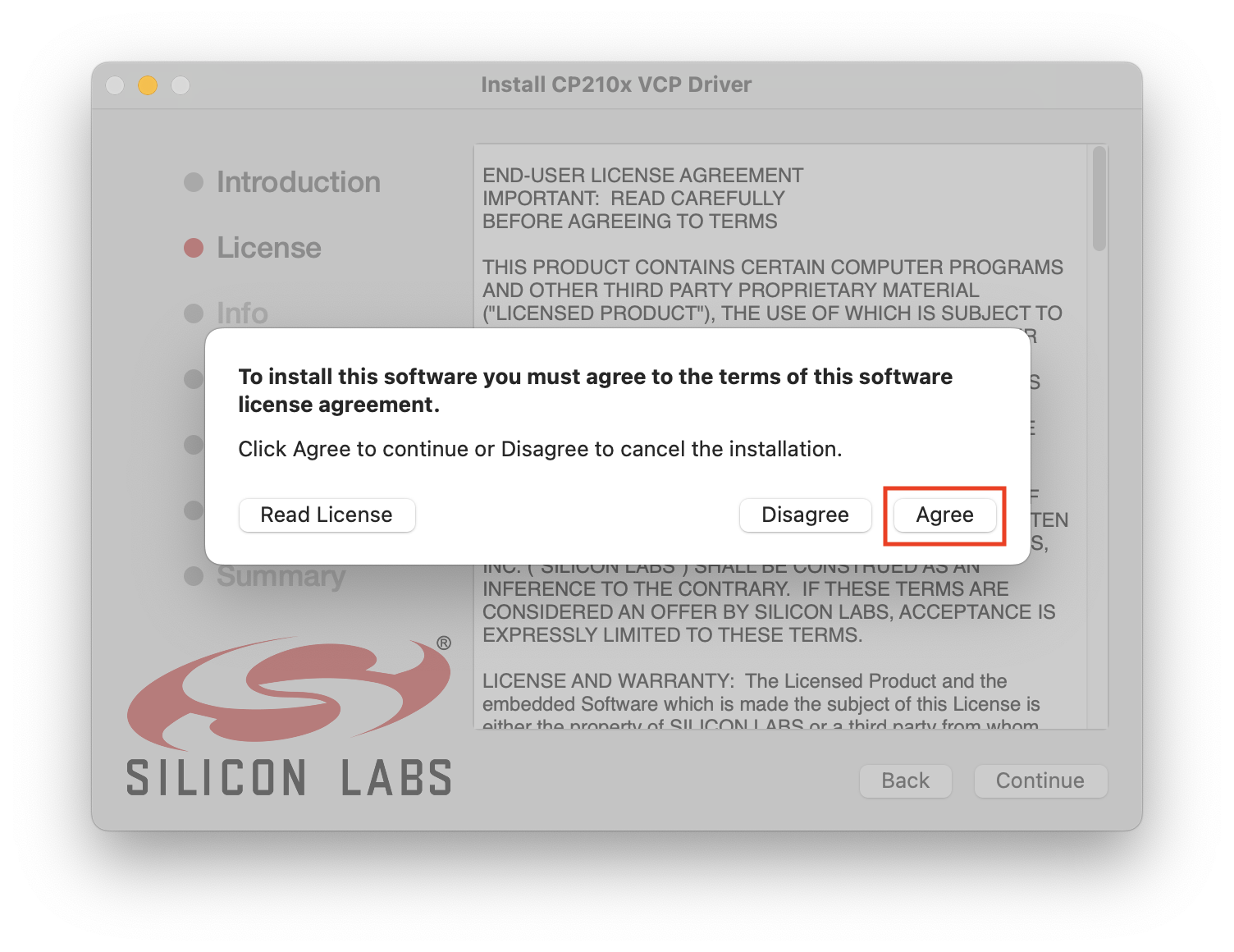
When the window opens, proceed with the installation as follows. 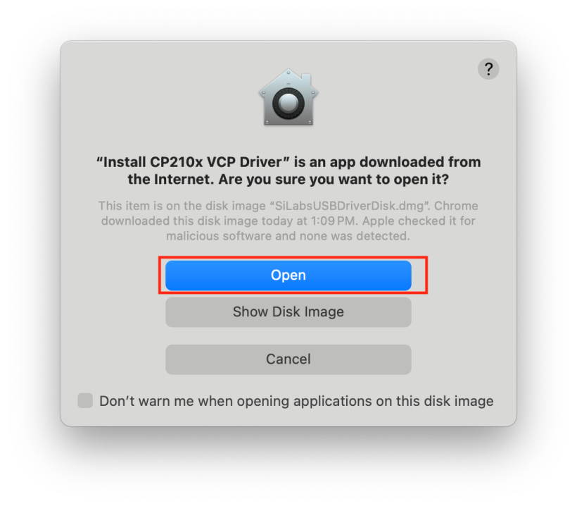
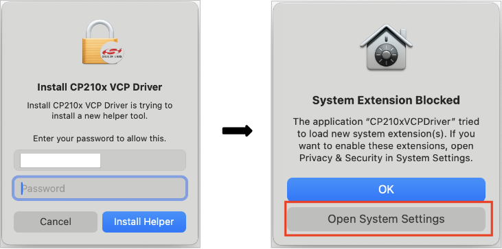
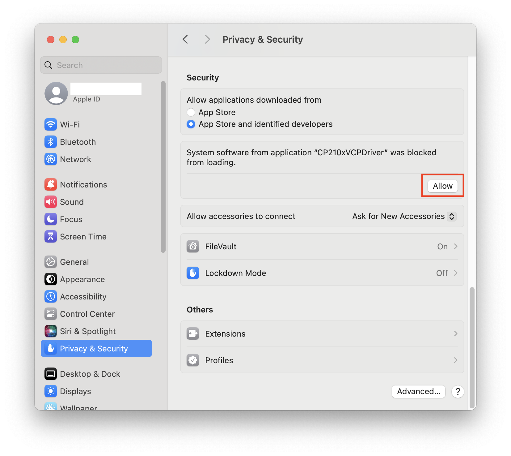
If a message like the one below appears, enter the password and click “Allow” for "CP201x VCP Driver" in [System Settings]-[Privacy & Security] to continue the installation.
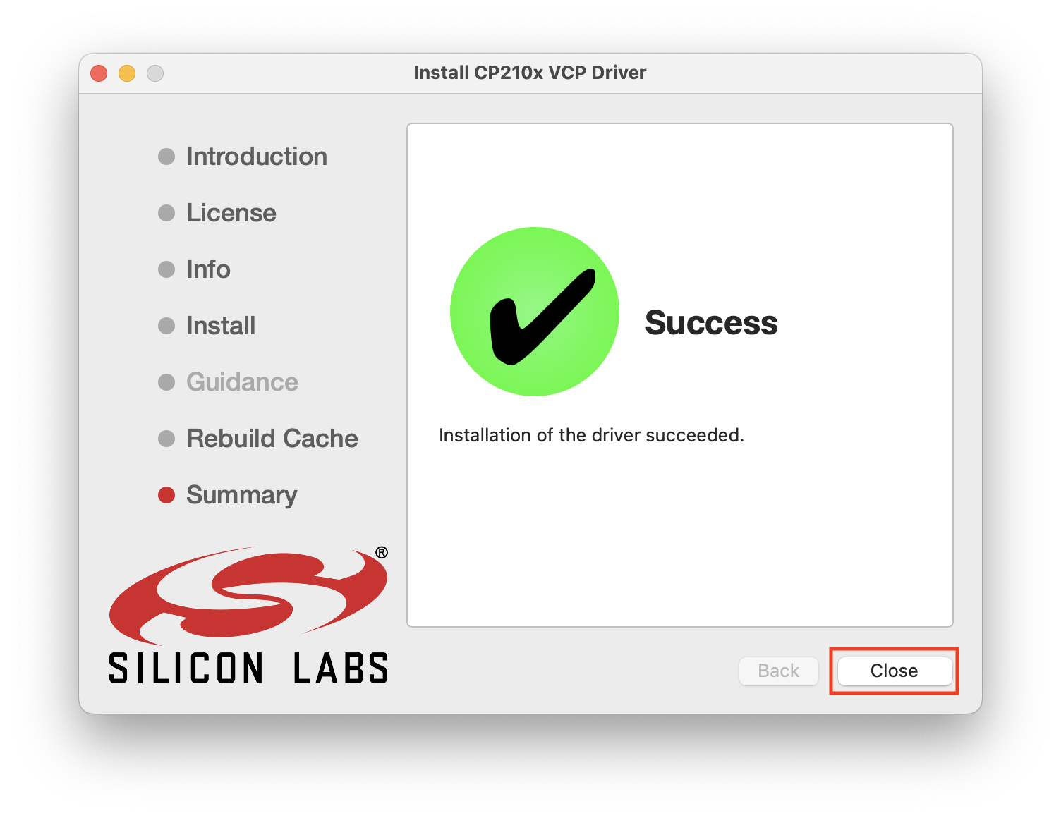
Step3. Check Driver installation Connect IR-USB03 to the USB port and select [System Information]->[Hardware]->[USB], you can find the connected device in the “USB Device Tree” on the right. If the USB device is working properly, the Model name will appear as shown in the figure below. 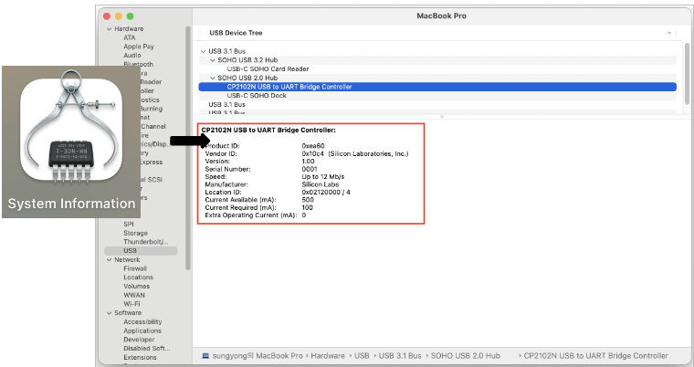
Step4. Check Comport Open the "Terminal" program in the [Application]-[Utility] folder and enter the following command: 
You will see "tty.usbserial-x", where "x" is the assigned device number, similar to Windows COM port assignments.
5.2 Total Manager software Installation Download the Total Manager Software from the Mightyzap homepage below and refer to the User Manual. https://mightyzap.com/en/digitalarchive6/
6. Basic Connection
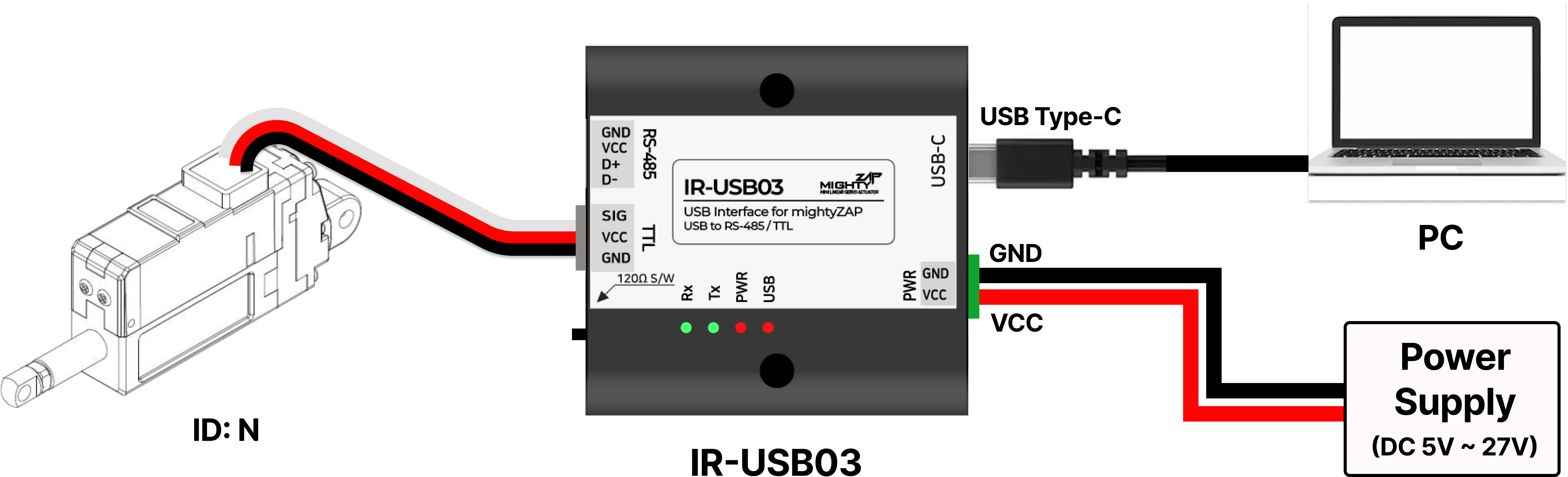
6.1 TTL Model
6.2 RS485 Model
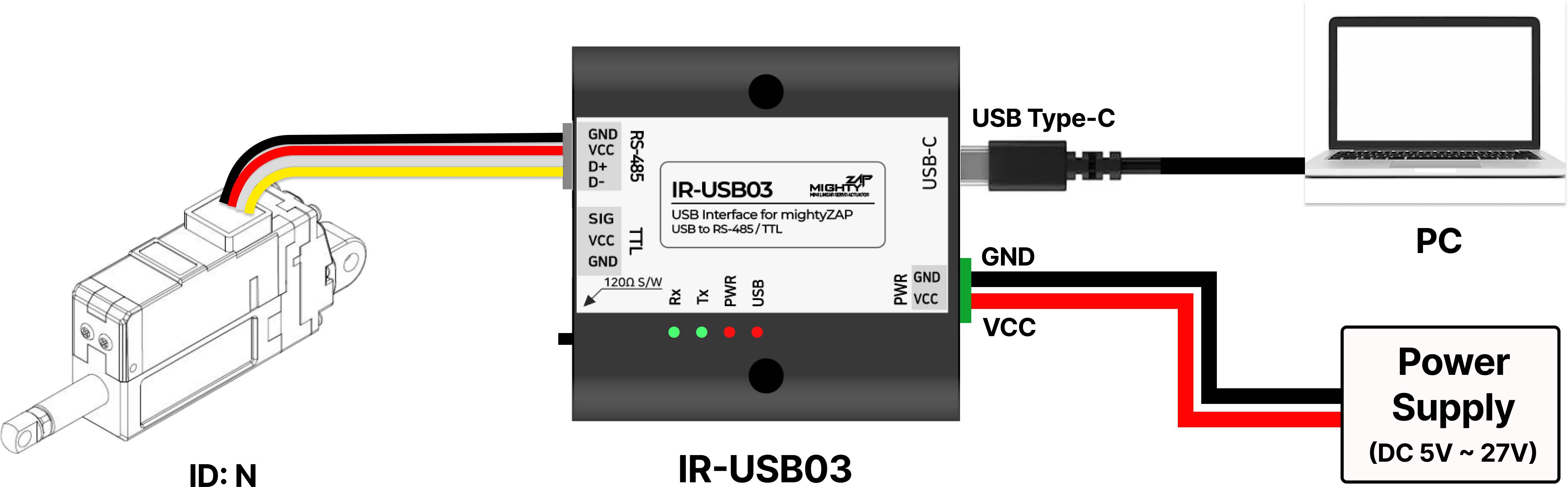
CAUTION!
- The rated input voltage for the D12, L12, 12Lf, and 17Lf series is 12 V. If voltage higher than 13 V is applied, the actuator may malfunction or be damaged. Be sure to check the rated input voltage of the actuator.
**CAUTION!**
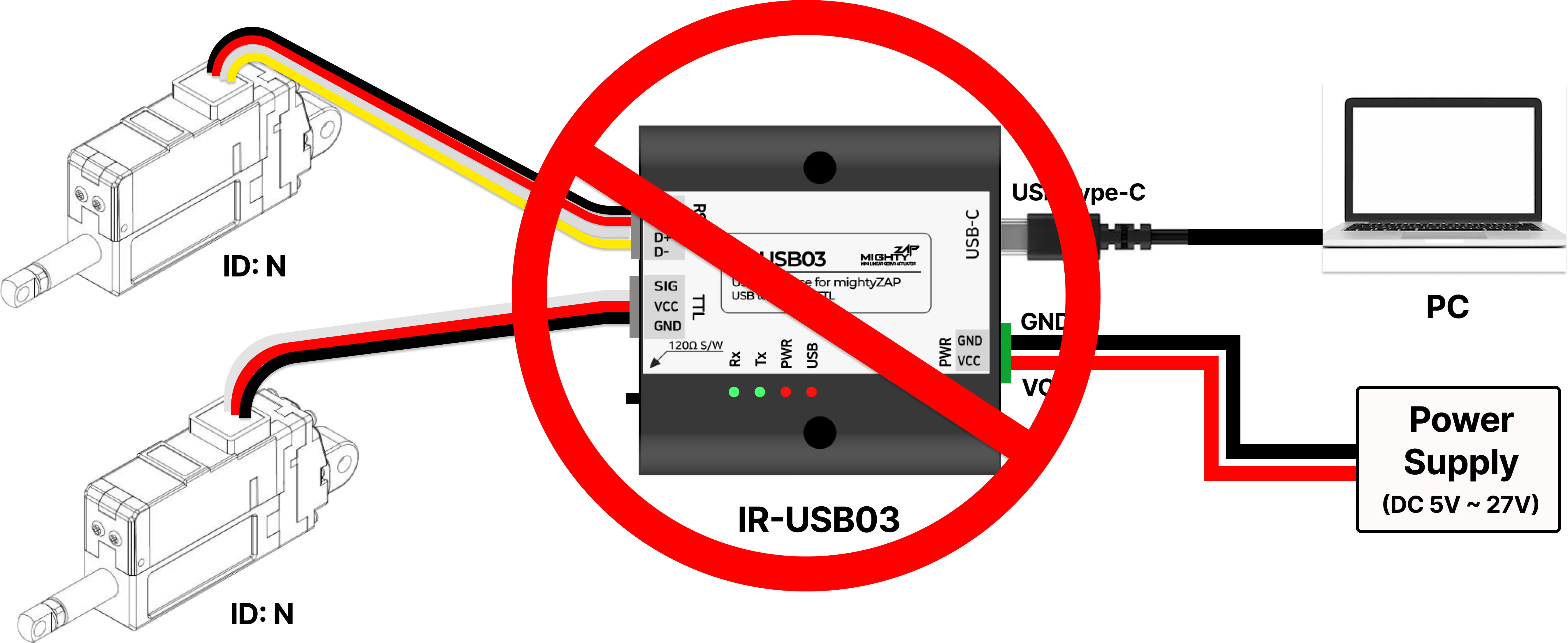
- It is not recommended to control TTL and RS485 models simultaneously.
7. Connect multiple actuators
7.1 Daisy-Chain Connection
When transmitting a Command Packet for ID N, only the actuator with ID N among several actuators returns the Feedback Packet and executes the command. 
7.2 More Connection
When using more than 5 actuators, supply actuator power separately from outside to ensure product stability. 
**WARNING!**
- Considering the basic Stall Current (Goal Current 800) of the actuator and the allowable current of the IR USB03 (4A), it is not recommended to connect more than 5 mightyZAP actuators to the single IR-USB03 at the same time.
- If the maximum current of the IR-USB03 is exceeded, there is a risk of PCB damage or fire. Therefore, if you must connect more than 5 actuators in series to the IR-USB03, power should be supplied from a separate external power source, not the USB03 as shown above.
8. RS-485 Terminating Resistor
What is the Termination Resistor?
- RS-485-based communication lines can cause communication errors due to the signal being reflected at the end of the transmission line in some cases. To prevent this, resistors (typically 120Ω) are inserted at both ends of the line to suppress signal reflection and noise. This resistor is called a termination resistor.
- The IR-USB03 provides a switch that can turn the built-in 120Ω termination resistor on / off so that it can be used in an RS-485 communication environment. Factory default is the off state, and you can consider using a termination resistor in the following cases.
- Long-distance communication environment (over 10m)
- High transmission speed (approximately 1Mbps or more) environment
- When multiple actuators are connected to the same node
- Industrial sites with severe ambient noise When intermittent communication signal errors occur
- Termination resistors generally only need to be installed at the beginning and end of the line.
- IR-USB03's termination resistor is internally connected only to the RS-485 circuit. The TTL communication models are nothing to do with termination resistors.
User needs to apply a termination resistor at both ends of the RS-485 network, and the resistance value is usually 120Ω. To suppress electrical noise, it is recommended to use a twisted wire for the RS-485 cable.
⁕ IR-USB03 has a built-in 120Ω termination resistor. (Switch On/Off)
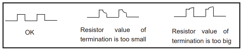
The best way to test after installing the termination resistor is to use an oscilloscope to directly check the RS-485 signal waveform, and the resistance value can be increased or decreased depending on the waveform.