17Bb Series User Manual
The contents of this manual may be subject to change before the official product release.
1. Product Introduction
1.1 Product Description
The mini17Bb is a linear servo motor with an integrated motor drive, combining a BLDC motor and an inductive linear encoder in a single housing.
Precise position and velocity control can be achieved using the CANopen (CiA 402) protocol without an external drive. Up to 127 nodes can be connected to a single bus, making it easy to configure multi-axis synchronous control systems.
Key features:
- BLDC motor
- Integrated inductive linear encoder
- Built-in drive (no external servo drive required)
- Compliant with the CANopen CiA 402 profile
- High-precision FOC (Field Oriented Control) current control
- Profile Position Mode (PP Mode) support
- Built-in software position limit and following error detection
- High-speed control loop based on the STM32G4 series
1.2 Product Specifications
1.2.1 Electrical Specifications
| Item | Specification |
|---|---|
| Rated Voltage | 24V DC |
| Operating Voltage Range | 12 - 34V DC |
| Rated Current | 650 mA |
| Maximum Current | 1600 mA |
| Communication Interface | CAN |
| Supported Baudrate | 125kbps, 250kbps, 500kbps, 1Mbps |
| Node-ID Range | 1 - 127 |
1.2.2 Mechanical Specifications
17Bb Servo Series Detailed Specifications
| Stroke | Rated Load (@450mA / Duty 100%) | Rated Load (@650mA / Duty 50%) | Max. Speed (No Load) | Model / Communication (CAN / RS-485) | Size (L×W×H / mm) | Weight | Gear Ratio |
|---|---|---|---|---|---|---|---|
| 30mm | 45N | 65N | 115 mm/s | 17Bb-65CF-30W | L130 × W28 × H63 | 485gf | 5:1 |
| 88N | 125N | 60 mm/s | 17Bb-125CF-30W | 10:1 | |||
| 200N | 280N | 28 mm/s | 17Bb-280CF-30W | 22:1 | |||
| 320N | 460N | 18 mm/s | 17Bb-460CF-30W | 36:1 | |||
| 520N | 750N | 11 mm/s | 17Bb-750CF-30W | 58:1 | |||
| 720N | 1000N | 7.2 mm/s | 17Bb-1000CF-30W | 83:1 | |||
| 60mm | 45N | 65N | 115 mm/s | 17Bb-65CF-60W | L166 × W28 × H63 | 580gf | 5:1 |
| 88N | 125N | 60 mm/s | 17Bb-125CF-60W | 10:1 | |||
| 200N | 280N | 28 mm/s | 17Bb-280CF-60W | 22:1 | |||
| 320N | 460N | 18 mm/s | 17Bb-460CF-60W | 36:1 | |||
| 520N | 750N | 11 mm/s | 17Bb-750CF-60W | 58:1 | |||
| 720N | 1000N | 7.2 mm/s | 17Bb-1000CF-60W | 83:1 | |||
| 100mm | 45N | 65N | 115 mm/s | 17Bb-65CF-100W | L216 × W28 × H63 | 645gf | 5:1 |
| 88N | 125N | 60 mm/s | 17Bb-125CF-100W | 10:1 | |||
| 200N | 280N | 28 mm/s | 17Bb-280CF-100W | 22:1 | |||
| 320N | 460N | 18 mm/s | 17Bb-460CF-100W | 36:1 | |||
| 520N | 750N | 11 mm/s | 17Bb-750CF-100W | 58:1 | |||
| 720N | 1000N | 7.2 mm/s | 17Bb-1000CF-100W | 83:1 | |||
| 150mm | 45N | 65N | 115 mm/s | 17Bb-65CF-150W | L270 × W28 × H63 | 720gf | 5:1 |
| 88N | 125N | 60 mm/s | 17Bb-125CF-150W | 10:1 | |||
| 200N | 280N | 28 mm/s | 17Bb-280CF-150W | 22:1 | |||
| 320N | 460N | 18 mm/s | 17Bb-460CF-150W | 36:1 | |||
| 520N | 750N | 11 mm/s | 17Bb-750CF-150W | 58:1 | |||
| 720N | 1000N | 7.2 mm/s | 17Bb-1000CF-150W | 83:1 |
2. Safety Precautions
Read this manual carefully before using the product. Failure to follow the safety instructions may result in product damage or personal injury.
2.1 Safety Symbols
| Symbol | Meaning |
|---|---|
| ⛔ DANGER | Failure to follow this instruction may result in death or serious injury. |
| ⚠ WARNING | Failure to follow this instruction may result in injury or product damage. |
| ℹ CAUTION | Important information that should be understood before use. |
2.2 Electrical Precautions
- ⚠ Never apply a voltage outside the permitted operating voltage range. Excessive voltage may damage the drive IC.
- ⚠ Always verify the power polarity (+/-). Reverse connection may damage the product.
- ℹ Check the CAN cable connection before applying power.
- ℹ Install 120Ω termination resistors at both ends of the CAN bus.
2.3 Mechanical Precautions
- ⚠ Do not apply an external force exceeding the rated thrust to the rod. Doing so may damage the encoder scale or internal mechanism.
- ⚠ Do not forcibly push or pull the rod. Doing so may damage the internal BLDC motor coil.
- ℹ Set the software position limit (0x607D) to prevent commands outside the available stroke range.
- ℹ Continuous overload conditions may increase internal temperature and shorten product life.
2.4 Handling Precautions
- ℹ Do not drop the product or subject it to impact.
- ℹ Avoid use in high-temperature, high-humidity, or excessively dusty environments.
- ℹ Do not disassemble or modify the product. Doing so will void the warranty.
3. Hardware Installation
3.1 Connector Pin Map
The mini17Bb provides power and CANopen communication through a single connector.
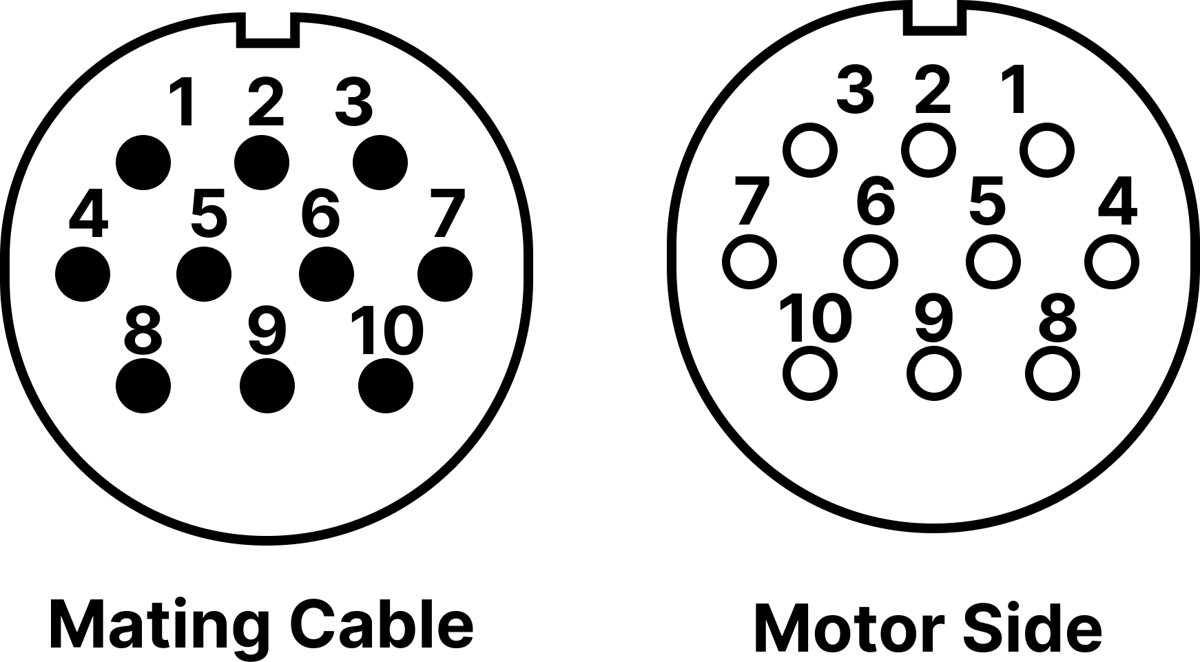
※ Viewed from the mating face (Front View)
| Pin No. | Signal | Color | Description |
|---|---|---|---|
| 1 | VCC | White | Power positive (+) |
| 2 | GND | Power negative (-), CAN GND | |
| 3 | I/O | Future support | |
| 4 | I/O | Future support | |
| 5 | I/O | Future support | |
| 6 | I/O | Future support | |
| 7 | RS485 | Future support | |
| 8 | RS485 | Future support | |
| 9 | CAN_H | Orange | CAN High |
| 10 | CAN_L | Orange dotted | CAN Low |
3.2 CAN Network Configuration
CANopen uses an ISO 11898-based two-wire differential signal (CAN_H / CAN_L).

3.2.1 Recommended Wiring: Daisy-Chain Connection
For CANopen communication, a daisy-chain (linear bus) topology is recommended, in which the communication line is connected continuously from one node to the next.
- Wiring structure: The communication line starts from the master controller, enters the IN port of the first motor (Node), and then continues from its OUT port to the IN port of the next motor.
- Termination resistor location: Install 120Ω termination resistors only at the two ends of the network: the first device (typically the master) and the last connected device.
To prevent signal reflections during bidirectional communication, install 120Ω (1/4W or higher) terminating resistors at both ends of the CANopen bus. Do not install termination resistors on intermediate nodes. A twisted-pair shielded cable is recommended for noise immunity, and the shield should be grounded at a single point on the master-controller side only.
3.2.2 Maximum Cable Length by Communication Speed
The total cable length of the CANopen network is physically limited by the selected baudrate. Higher communication speeds are more sensitive to propagation delay and signal attenuation. Select an appropriate baudrate based on the total network length.
Recommended Stub Length by Baudrate
| Baudrate | Maximum Length of a Single Stub | Total Cumulative Stub Length |
|---|---|---|
| 1 Mbps | 0.3 m (30 cm) | 1.5 m or less |
| 500 kbps | 1.2 m | 6.0 m or less |
| 250 kbps | 2.4 m | 12.0 m or less |
| 125 kbps | 4.8 m | 24.0 m or less |
※ Maximum single stub length: maximum cable length from a T-connector to one motor (node).
※ Total cumulative stub length: sum of the lengths of all stub cables in the network.
Stub Cable Length Limitation for T-Connector Wiring: A stub branching from a T-connector to an individual controller can cause high-frequency signal reflections, so it should be kept as short as possible. For stable communication, comply with the maximum allowable lengths shown above.
Termination Resistance by Communication Speed
- This table assumes fewer than 64 connected nodes (motors, controllers, etc.).
- The values are based on CiA 303-1.
- Select termination resistance, cable, and communication speed according to the bus length.
| Bus Length [m] | Resistance per Unit Length [mΩ/m] | Wire Cross-Section [mm²] | Termination Resistance [Ω] | Bit Rate | Notes / Recommendation |
|---|---|---|---|---|---|
| 0 to 40 | 70 | 0.25 to 0.34 | 124 | 1000 kbps (at 40m) | Strictly follow noise shielding and daisy-chain wiring rules |
| 40 to 300 | <60 | 0.24 to 0.6 | 150 to 300 | ≤500 kbps (at 100m) | Recommended standard speed for industrial applications (Default) |
| 300 to 600 | <40 | 0.5 to 0.6 | 150 to 300 | <100 kbps (at 500m) | Easier to secure stability with many connected devices |
| 600 to 1000 | <26 | 0.75 to 0.8 | 150 to 300 | <50 kbps (at 1km) | For long-distance control networks |
- Recommended cable parameters: 120Ω characteristic impedance, specific line delay 5ns/m.
- A 120Ω termination resistor is normally used for short CAN networks. For long-distance networks, follow the recommended values in the CiA 303-1 table above to reduce voltage drop.
- The table represents maximum wiring length according to the number of bus nodes and conductor cross-sectional area.
3.2.3 Communication Speed and Node-ID Setting
The communication speed and Node-ID can be changed in software through the internal Object Dictionary parameters.
Parameter indexes
- Node-ID: Index 0x2001
- Baudrate: Index 0x2002
Procedure for changing and applying the communication speed
Network parameters such as baudrate do not take effect immediately after the value is changed. Follow these three steps:
- Write: Use SDO (Service Data Object) communication from the master to write the desired baudrate setting value to the relevant index (for example, 1Mbps = 0, 500kbps = 1).
- Save to non-volatile memory: Execute Index 0x1010 (Store Parameters) so the changed value remains after power is removed.
- Reset: Power-cycle the controller or execute the NMT Reset Node command. The new baudrate is applied after reset.
For the exact input mapping values (Data Value) for each communication speed and detailed SDO setting protocol, refer to Section 9.2, Manufacturer Specific Parameters.
4. CANopen Communication Overview
CANopen is a higher-layer communication protocol developed to improve interoperability between industrial devices based on CAN (Controller Area Network), which is widely used in automotive systems. It is maintained by CiA (CAN in Automation).
The basic concept of CANopen is that every device contains a standardized data structure called an Object Dictionary. Real-time control data is transferred through PDOs (Process Data Objects) using a Producer-Consumer structure with minimal protocol overhead, while configuration data is read and written through SDOs (Service Data Objects).
4.1 SDO (Service Data Object)
SDO is mainly used for configuration and larger data transfers.
4.1.1 Key Features
- Direct access to the Object Dictionary: The client directly reads or writes specific entries in the server's Object Dictionary.
- Client-server structure: SDO creates a one-to-one communication channel. The device owning the Object Dictionary is the server, and the client always initiates communication.
- Multiplexer: The client specifies data using the Object Dictionary Index and Sub-index.
- Abort: Either the client or server may abort communication as required.
4.1.2 Data Transfer Mechanism
SDO is designed to transfer large data blocks without being limited to a single CAN frame.
- Segmented transfer: Data may be divided into multiple segments and transmitted sequentially after an initialization phase.
- Expedited Transfer: When the data size is 4 bytes or less, the data can be transmitted directly during the initialization phase without segmentation.
4.2 PDO (Process Data Object)
PDO is used for the most important real-time data transfer in a control system.
4.2.1 Key Features
- Real-time performance: PDO transmits process data without additional protocol overhead, providing fast and efficient communication.
- Producer-Consumer structure: The device transmitting a PDO acts as a producer (TPDO), while the receiving device acts as a consumer (RPDO).
- TPDO (Transmit-PDO): Used when the device sends data.
- RPDO (Receive-PDO): Used when the device receives data.
4.2.2 Mapping and Parameter Structure
Each PDO is defined through two parameter groups:
- PDO Mapping: Defines which application data and data types are included in the PDO. Variable PDO mapping can be modified through SDO communication.
- PDO Communication Parameter: Defines how the PDO communicates, including transmission type and timing.
4.3 SDO and PDO Comparison
| Item | SDO | PDO |
|---|---|---|
| Main Purpose | Device setup, diagnostics, larger data transfer | Real-time process/control data |
| Communication Speed | Slower due to initialization/segmentation | Very fast, minimal overhead |
| Data Size | Not limited to one PDO frame | Normally up to 8 bytes |
| Communication Structure | Client-Server (1:1) | Producer-Consumer |
| Operation | Started by client request | Triggered according to mapping/event conditions |
| Object Dictionary | Direct Index/Sub-index access | Data grouped according to PDO mapping |
5. NMT State Machine
5.1 NMT State Diagram
After power-up, a CANopen device is managed by the NMT (Network Management) state machine.
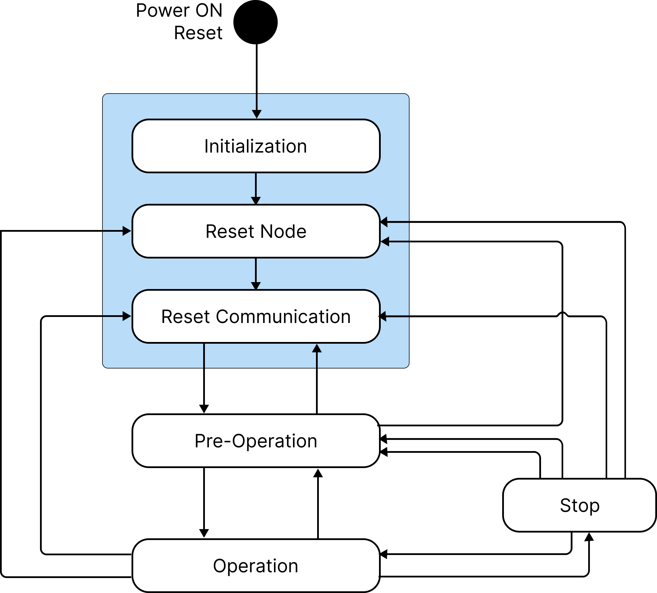
| NMT State | Description | PDO | SDO | EMCY |
|---|---|---|---|---|
| Initialization | Parameter loading and internal initialization | ✗ | ✗ | ✗ |
| Pre-Operational | Configuration state; parameters can be set using SDO | ✗ | ✓ | ✓ |
| Operational | Operating state; all communication objects active | ✓ | ✓ | ✓ |
| Stopped | Stopped state; only NMT messages are received | ✗ | ✗ | ✗ |
5.2 CiA 402 Drive State Machine
A CANopen CiA 402 servo drive is controlled through 6040h (Controlword) and 6041h (Statusword).
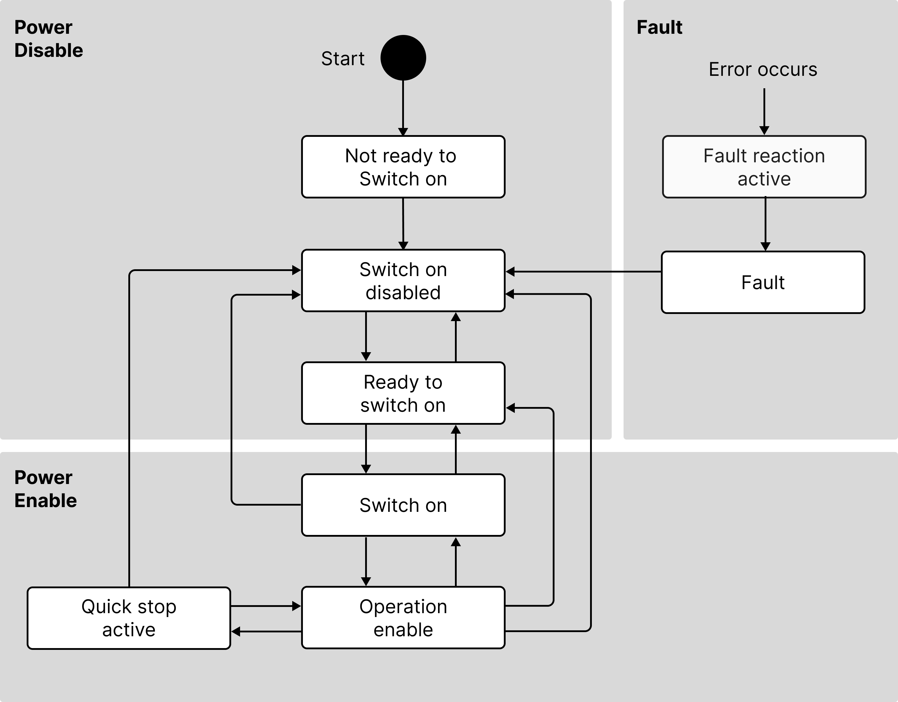
Controlword State Transition Summary
| Target Transition | Bit 3 | Bit 2 | Bit 1 | Bit 0 | Controlword |
|---|---|---|---|---|---|
| Shutdown (→ Ready to Switch On) | - | 1 | 1 | 0 | 0x0006 |
| Switch On (→ Switched On) | 0 | 1 | 1 | 1 | 0x0007 |
| Enable Operation (→ Operation Enabled) | 1 | 1 | 1 | 1 | 0x000F |
| Disable Voltage | - | - | 0 | - | 0x0000 |
| Quick Stop | - | 0 | 1 | - | 0x0002 |
| Fault Reset | 0→1 rising edge | 0x0080 |
6. Drive and Operation Mode Guide
The mini17Bb linear servo motor can operate only after passing through the internal CiA 402 state machine after power-up. This section explains the basic sequence for enabling the motor and moving it to a target position.
6.1 Drive Enable Sequence
To place the motor in the Operation Enabled state, 0x6040 (Controlword) must be changed sequentially.
| Step | Target State | 0x6040 Value | Description |
|---|---|---|---|
| 1 | Shutdown | 0x0006 | Prepares the drive power stage (Ready to Switch On) |
| 2 | Switch On | 0x0007 | Enables power for motor operation (Switched On) |
| 3 | Enable Operation | 0x000F | Fully enables the drive so it can execute commands |
After each step, read 0x6041 (Statusword) and verify that the drive has reached the intended state before sending the next command.
6.2 Profile Position (PP) Mode
Profile Position (PP) Mode is commonly used for point-to-point positioning. The master sets the target position, velocity, acceleration, and deceleration parameters, and the drive's internal profile generator calculates a smooth motion profile.
1. Main Motion Parameters
| Index | Parameter | Description | Note |
|---|---|---|---|
| 0x6060 | Modes of Operation | Selects the operation mode | Set to 1 (PP Mode) |
| 0x6081 | Profile Velocity | Sets maximum travel velocity | Required |
| 0x6083 | Profile Acceleration | Sets acceleration | Required |
| 0x6084 | Profile Deceleration | Sets deceleration | Required |
| 0x607A | Target Position | Final target position | Set before motion command |
2. PP Mode-Specific Controlword (0x6040)
In PP Mode, Bits 4, 5, 6, and 9 of 0x6040 have specific meanings.
- Bit 4 (New Set-point): A 0→1 rising edge starts motion toward the target position stored in 0x607A.
- Bit 5 (Change Set Immediately):
0: Move to the new target after completing the current move.1: Interrupt the current move and immediately change the trajectory toward the new target.
- Bit 6 (Absolute / Relative):
0: Absolute positioning.1: Relative positioning from the current position.
- Bit 9 (Change of Setpoint): When Bit 5 = 0, determines whether the next target is executed continuously without stopping after the current move.
3. Operation Methods
Single set point — Future support
- Stop after reaching the target and wait for the next command.
- Setting: Bit 4 = 1, Bit 5 = 0, Bit 9 = 0
Change immediately
- When a new position command is received during motion, the existing target is discarded and the trajectory is immediately changed.
- Setting: Bit 4 = 1, Bit 5 = 1
Set of Set point — Future support
- When a new position command is received during motion, complete the current target and continue to the next target without stopping.
- Setting: Bit 4 = 1, Bit 5 = 0, Bit 9 = 1
4. Step-by-Step Motion Sequence
- Set 0x6060 = 1 to enter PP Mode.
- Set the required motion profile values in 0x6081, 0x6083, 0x6084, and 0x607A.
- Verify that the drive is in Operation Enabled state (Controlword 0x000F).
- Send 0x001F to the Controlword to activate Bit 4 and start motion (absolute positioning example).
- Verify that Statusword Bit 12 (Set-point Acknowledge) becomes 1.
- Return the Controlword to 0x000F (Bit 4 = 0) to prepare for the next command.
- When the motor reaches the target within the specified tolerance, Statusword Bit 10 (Target Reached) becomes 1.
7. Error Handling and Diagnostics
7.1 Error Check and Recovery
When an error occurs during servo operation, the drive immediately stops and enters the Fault state, and an EMCY message is transmitted. The current fault state can be checked through Bit 3 (Fault) of 0x6041 (Statusword), and the detailed cause can be read from 0x603F (Error Code).
Fault Reset: After identifying and correcting the physical cause of the error, change Bit 7 (Fault Reset) of 0x6040 from 0 to 1 (for example, send 0x0080).
7.2 Main Error Codes
7.2.1 CiA 301 Error Code
| Error Code | Name | Error | Condition |
|---|---|---|---|
| 0x0000 | ERROR NONE | No error |
7.2.2 CiA 402 Error Code
| Error Code | Name | Error | Condition |
|---|---|---|---|
| 0x0000 | ERROR NONE | No error | Normal state |
| 0x3110 | DC Link Over Voltage | Overvoltage | Input voltage remains above VOLTAGE_OVER_LIMIT (34.0V) for 25ms or longer |
| 0x3120 | DC Link Under Voltage | Undervoltage | Input voltage remains below VOLTAGE_UNDER_LIMIT (10.0V), but above the power-off threshold (1.0V), for 25ms |
| 0x2310 | Over Current | Overcurrent | Phase current exceeds the hardware limit or Max Current × 1.5, or excessive power-supply current is detected for 7.5ms or longer |
| 0x5000 | Hardware Failure | Hardware failure | The motor driver (DRV8316) detects a critical fault and the nFault pin remains Low for approximately 25ms |
| 0x8611 | Position Following Error | Following error | Difference between Target Position and Actual Position exceeds the configured window for longer than the configured timeout |
8. Current Monitoring and Stall Protection
If the motor is mechanically blocked, motor current may increase up to the configured limit as the drive attempts to maintain the required torque. Prolonged stall conditions may increase motor and drive temperature and reduce product life. Use appropriate protection settings such as Following Error detection.
8.1 Real-Time Current Monitoring
0x6078 (Current Actual Value) provides the actual motor phase current in mA. This is not the DC line current consumed from the power supply; it represents the effective motor current generating torque and can be used to monitor load variation and mechanical friction.
8.2 Obstacle Collision and Stall Protection
If the servo motor hits an obstacle and stalls before reaching the target position, motor back-EMF decreases and a temporary high-current condition can occur.
When the mini17Bb detects a stall condition, internal protection control limits voltage and current to protect the hardware. A high-frequency motor-coil noise (whine) may occur during protection and can be part of the normal protection mechanism. To avoid prolonged stall conditions, appropriately configure Following Error (0x6065) detection so the controller can stop when abnormal motion is detected.
9. Object Dictionary
9.1 Communication Area (CiA 301)
Object Dictionary Quick Reference
| Index (Hex) | Object Name | Description |
|---|---|---|
| 1000h | Device Type | CiA-defined device type (actuator example: 0x00000192) |
| 1001h | Error Register | Current error-state register |
| 1003h | Pre-defined Error Field | Stores error history |
| 1008h | Manufacturer Device Name | Manufacturer device name |
| 1009h | Manufacturer Hardware Version | Hardware version |
| 100Ah | Manufacturer Software Version | Firmware version |
| 1010h | Store Parameters | Parameter save command |
| 1011h | Restore Default Parameters | Restore default parameters |
| 1017h | Producer Heartbeat Time | Heartbeat generation period in ms |
| 1018h | Identity Object: Vendor ID | Official vendor ID |
| 1018h | Identity Object: Product Code | Manufacturer-assigned product code |
| 1018h | Identity Object: Revision Number | Product revision number |
| 1018h | Identity Object: Serial Number | Product serial number |
| 1014h | COB-ID EMCY | EMCY COB-ID (Node-ID + 0x80) |
| 1200h | SDO Server Parameter | SDO server communication parameter |
| 1400h | 1st Receive PDO Parameter | RPDO1 communication parameter |
| 1401h | 2nd Receive PDO Parameter | RPDO2 communication parameter |
| 1402h | 3rd Receive PDO Parameter | RPDO3 communication parameter |
| 1403h | 4th Receive PDO Parameter | RPDO4 communication parameter |
| 1600h | 1st Receive PDO Mapping | RPDO1 mapping |
| 1601h | 2nd Receive PDO Mapping | RPDO2 mapping |
| 1602h | 3rd Receive PDO Mapping | RPDO3 mapping |
| 1603h | 4th Receive PDO Mapping | RPDO4 mapping |
| 1800h | 1st Transmit PDO Parameter | TPDO1 communication parameter |
| 1801h | 2nd Transmit PDO Parameter | TPDO2 communication parameter |
| 1802h | 3rd Transmit PDO Parameter | TPDO3 communication parameter |
| 1803h | 4th Transmit PDO Parameter | TPDO4 communication parameter |
| 1A00h | 1st Transmit PDO Mapping | TPDO1 mapping |
| 1A01h | 2nd Transmit PDO Mapping | TPDO2 mapping |
| 1A02h | 3rd Transmit PDO Mapping | TPDO3 mapping |
| 1A03h | 4th Transmit PDO Mapping | TPDO4 mapping |
For more information on CiA 301, refer to http://www.canopener.org/.
9.2 Manufacturer Specific Parameters
The range 0x2000 to 0x2FFF is reserved for mini17Bb manufacturer-specific parameters.
9.3 Drive Profile (CiA 402)
CiA 402 Object Dictionary Quick Reference
| Index | Sub-index | Object Name | Description |
|---|---|---|---|
| 6061h | 00h | Modes of Operation Display | Current operation mode |
| 6062h | 00h | Position Demand Value | Position-controller target position |
| 6063h | 00h | Position Actual Internal Value | Internal position value |
| 6064h | 00h | Position Actual Value | Actual position in user units |
| 6065h | 00h | Following Error Window | Allowable following-error window |
| 6066h | 00h | Following Error Timeout | Allowable following-error duration |
| 6067h | 00h | Position Window | Position target tolerance |
| 6068h | 00h | Position Window Time | Minimum duration inside Position Window |
| 606Ch | 00h | Velocity Actual Value | Current servo velocity |
| 6072h | 00h | Max Torque | Maximum motor torque |
| 6073h | 00h | Max Current | Maximum motor current |
| 6076h | 00h | Motor Rated Torque | Rated motor torque |
| 6077h | 00h | Torque Actual Value | Current motor torque |
| 6079h | 00h | DC Link Circuit Voltage | Power monitoring in 0.1V units |
| 607Ah | 00h | Target Position | Final target position for PP control |
| 607Dh | 00h | Software Position Limit (Number of entries) | Number of software position limit entries |
| 607Dh | 01h | Min Position Limit | Minimum target position |
| 607Dh | 02h | Max Position Limit | Maximum target position |
| 607Fh | 00h | Max Profile Velocity | Maximum PP-mode velocity |
| 6080h | 00h | Max Motor Speed | Maximum linear speed |
| 6081h | 00h | Profile Velocity | PP-mode profile velocity |
| 6083h | 00h | Profile Acceleration | PP-mode profile acceleration |
| 6084h | 00h | Profile Deceleration | PP-mode profile deceleration |
| 6085h | 00h | Quick Stop Deceleration | Deceleration used for Quick Stop |
| 60F4h | 00h | Following Error Actual Value | Real-time following error |
| 60FCh | 00h | Position Demand Internal Value | Internal demanded position |
| 60FDh | 00h | Digital Inputs | Digital input state |
| 60FEh | 00h | Digital Outputs | Digital output state |
| 6502h | 00h | Supported Drive Modes | Supported operation modes |
10. Object Dictionary Details
10.1 Communication Profile (CiA 301)
Objects in the 0x1000 range are defined by the CiA 301 Communication Profile.
0x1000: Device Type
What is the 0x1000 Device Type? This object is like the device's "ID card." By reading this value, the master can immediately recognize that "this device is a servo drive that follows the CiA 402 standard." The 32-bit value includes the device profile number and additional functional information.
This value is set as a fixed value in the firmware by the developer according to the CiA standard for the device type.
- Value structure:
- Lower 16 bits: Device profile number. Because a servo drive follows the CiA 402 profile, this value is 402 (hexadecimal: 0x0192).
- Upper 16 bits: Additional information (manufacturer-specific function information). If there is no special information, this is set to 0x0000.
- Example final setting value (servo drive):
0x00000192
| Index | Description | Type | Setting Range | Default | Unit | Access | PDO Mapping | Change Condition | Save |
|---|---|---|---|---|---|---|---|---|---|
| 0x1000 | Device Type | UINT32 | - | 0x00000192 | - | RO | No | - | No |
0x1001: Error Register
What is the 0x1001 Error Register? It is a standard 8-bit (1-byte) object that summarizes the current error state of a CANopen device (node) at a glance. The master (for example, a PLC or controller) can read this object through SDO communication to quickly determine what type of error has occurred in the device.
| Index | Description | Type | Setting Range | Default | Unit | Access | PDO Mapping | Change Condition | Save |
|---|---|---|---|---|---|---|---|---|---|
| 0x1001 | Error Register | USINT | - | 0x00 | - | RO | No | - | No |
Bit Definition
| Bit No. | Name | Description |
|---|---|---|
| Bit 0 | Generic Error | Set to 1 when any type of error listed below occurs. (Error summary bit) |
| Bit 1 | Current | Indicates a motor-current-related error such as overcurrent. (Required for servo motors) |
| Bit 2 | Voltage | Indicates a power-voltage-related error such as overvoltage or undervoltage. (Required for servo motors) |
| Bit 3 | Temperature | Indicates a temperature-sensor-related error such as overheating. (Required for servo motors) |
| Bit 4 | Communication Error | Indicates a CAN communication supervision error such as Heartbeat or Guarding failure. |
| Bit 5 | Device Profile Specific | Indicates an error defined by a specific profile such as CiA 402 (motion control). |
| Bit 6 | Reserved | Not used and always 0. |
| Bit 7 | Manufacturer Specific | Indicates a manufacturer-defined error not included in the standard. |
0x1003: Pre-defined Error Field
The Pre-defined Error Field is an array-type object that stores the history of errors that have occurred in the device.
This object is filled by recording error codes sequentially whenever errors occur and is very useful for diagnosing past problems with the equipment.
While the Error Register shows the device's current error state, the 0x1003 Error Field is a log storage area that records the past errors experienced by the device in sequence. It is important for remote diagnostics and maintenance because it allows the user to trace what happened and in what order when a problem occurred. This object has an array structure, and each index has the following meaning:
- 0x1003:00 (Sub-index 0): Number of stored errors (UNSIGNED8)
- Reading this value shows how many errors are currently recorded. It may also indicate the maximum number of errors that can be stored.
- 0x1003:01 to 0x1003:n (Sub-index 1 to n): Actual error codes (UNSIGNED32)
- The 32-bit standard error codes that occurred in the device are stored in the order of occurrence. The first error is recorded in 0x1003:01 and the second in 0x1003:02.
0x1008: Manufacturer Device Name
Device Name is an object that stores a human-readable string name used to identify the device.
Its main purpose is for use in CANopen network configuration tools or monitoring software. When a tool scans the network, it reads each device's 0x1008 object and can display an easy-to-understand name such as "X-Axis Servo Drive" instead of simply "Node 3." This is very convenient when configuring the system or diagnosing problems.
| Index | Description | Object | Data Type | Access | PDO Mapping | Change Condition | Save | Default |
|---|---|---|---|---|---|---|---|---|
| 0x1008 | Device Name | VARIABLE | STRING | RO | No | N/A | No | (Product name) |
0x1009: Manufacturer Hardware Version
Hardware Version is a human-readable string object that indicates the physical PCB (circuit-board) revision or hardware specification of the device. It is very important for tracking problems that occur only with a particular hardware version or for accurately identifying a customer's product specification during technical support.
| Index | Description | Object | Data Type | Access | PDO Mapping | Change Condition | Save | Default |
|---|---|---|---|---|---|---|---|---|
| 0x1009 | Hardware Version | VARIABLE | STRING | RO | No | N/A | No | (Version) |
0x100A: Manufacturer Software Version
Software Version is a human-readable string object that indicates the version of the firmware currently running in the device.
| Index | Description | Object | Data Type | Access | PDO Mapping | Change Condition | Save | Default |
|---|---|---|---|---|---|---|---|---|
| 0x100A | Software Version | VARIABLE | STRING | RO | No | N/A | No | (Version) |
0x1010: Store Parameters
Store Parameters is an object used to command the device to permanently save its current settings (parameters) to non-volatile memory such as EEPROM or Flash.
The save operation is executed by writing the code meaning "save" (0x65766173) to a specific Sub-index. (ASCII values: s=0x73, a=0x61, v=0x76, e=0x65)
This object performs exactly the same role as a software Save button. When a user changes various parameters such as motor gain values or communication periods through SDO communication, those changes are first stored temporarily in RAM. If the device is power-cycled at this point, the RAM contents disappear and the changes are lost.
When a save command is issued to object 0x1010, the device copies the current settings in RAM to non-volatile memory (NVM) for permanent storage. As a result, the last saved settings are retained even after the device is rebooted.
| Index | Description | Data Type | Setting Range | Default | Unit | Access | PDO Mapping | Change Condition | Save |
|---|---|---|---|---|---|---|---|---|---|
| 0x1010 | Store Parameters | ||||||||
| 0x1010:0 | Number of entries | - | 4 | - | RO | No | N/A | No | |
| 0x1010:1 | Store all parameters | 0x0 to 0xFFFFFFFF | 0 | - | RW | No | N/A | No | |
| 0x1010:2 | Store communication parameters | 0x0 to 0xFFFFFFFF | 0 | - | RW | No | N/A | No | |
| 0x1010:3 | Store CiA402 parameters | 0x0 to 0xFFFFFFFF | 0 | - | RW | No | N/A | No | |
| 0x1010:4 | Store drive specific parameters | 0x0 to 0xFFFFFFFF | 0 | - | RW | No | N/A | No |
0x1017: Producer Heartbeat Time
Producer Heartbeat Time sets how often the device sends a heartbeat signal to the network to indicate that it is alive.
At each interval set here, the device transmits a heartbeat message containing its NMT state (Pre-Operational, Operational, Stopped, etc.) to the network. By receiving this message periodically, the master controller can determine that the device is connected and operating normally.
If the master does not receive the heartbeat message within the expected time, it can determine that a problem has occurred in the servo drive and take emergency action such as safely stopping the system.
| Index | Description | Data Type | Setting Range | Default | Unit | Access | PDO Mapping | Change Condition | Save |
|---|---|---|---|---|---|---|---|---|---|
| 0x1017 | Producer heartbeat time | UINT16 | - | 0 | ms | RW | No | - | - |
- A Heartbeat value of
0means that the function is disabled.
0x1018: Identity Object
The Identity Object is a record-type object that collects the device's key identification information, including manufacturer ID, product code, version, and serial number. A network management tool can read this object to determine at once which company's product the device is, as well as its version and serial number.
| Index | Description | Data Type | Setting Range | Default | Unit | Access | PDO Mapping | Change Condition | Save |
|---|---|---|---|---|---|---|---|---|---|
| 0x1018 | Identity Object | ||||||||
| 0x1018:0 | Number of entries | UINT8 | - | 4 | - | RO | No | - | No |
| 0x1018:1 | Vendor ID | UINT32 | - | - | RO | No | - | No | |
| 0x1018:2 | Product code | UINT32 | - | - | RO | No | - | No | |
| 0x1018:3 | Revision number | UINT32 | - | - | RO | No | - | No | |
| 0x1018:4 | Serial number | UINT32 | - | - | RO | No | - | No |
0x1400-0x1403: Receive PDO 1-4 Communication Parameter
Object 0x1400 defines the communication method of the first Receive PDO (RPDO) received by the device. An RPDO is a high-speed data packet containing real-time control commands such as target position, velocity, and Controlword. This object defines which CAN ID is used to receive the packet and at what timing (synchronous/asynchronous) it is processed.
PDO (Process Data Object) is a core CANopen mechanism for high-speed exchange of real-time data. While SDO is 1:1 communication for configuration, PDO is closer to 1:N broadcast communication for real-time control.
Object 0x1400 defines the "envelope" information of the first command packet (RPDO1). In other words, it sets the "destination address (CAN ID)" written on the envelope and the "delivery method (synchronous/asynchronous)." The data contained in the RPDO—the "letter contents"—are defined separately in the corresponding 0x1600 (1st Receive PDO Mapping) object.
| Index | Description | Data Type | Setting Range | Default | Unit | Access | PDO Mapping | Change Condition | Save |
|---|---|---|---|---|---|---|---|---|---|
| 0x1400 | 1st receive PDO Parameter | ||||||||
| 0x1400:0 | Number of entries | - | 5 | - | RO | No | - | No | |
| 0x1400:1 | COB-ID used by RPDO | INT32 | - | NODEID + 0x200 | - | RW | No | - | Yes |
| 0x1400:2 | Transmission type | UINT8 | - | 254 | - | RW | No | - | Yes |
| 0x1400:5 | Event Time | UINT16 | - | - | RW | No | - | Yes |
Main Setting Details
- COB-ID (0x1400:01)
- The default ID rule is
0x200 + Node-ID. For example, the first RPDO receive ID of a servo with Node-ID=5 is0x205. The master must transmit the RPDO using this ID.
- The default ID rule is
- Transmission Type (0x1400:02)
- 1 to 240 (synchronous): RPDO data are processed whenever a SYNC message is received. A value of 1 means process every SYNC, while 5 means process every 5th SYNC. This is used for precise simultaneous control.
- 254 or 255 (asynchronous): RPDO data are processed immediately when the RPDO message is received, regardless of the SYNC signal.
- Operating Flow (for a servo with Node-ID = 5)
- Mapping setting (0x1600): First define which data are contained in RPDO1. For example, map Controlword (0x6040) and Target Position (0x607A) in object 0x1600.
- Communication setting (0x1400):
- Set 0x1400:01 (COB-ID) to the default value
0x205. - Set 0x1400:02 (Transmission Type) to
1so that the data are processed at every SYNC.
- Set 0x1400:01 (COB-ID) to the default value
0x1600-0x1603: 1st-4th Receive PDO Mapping
Object 0x1600 is the "blueprint" or "table of contents" that defines which data are contained in the first Receive PDO (RPDO1) and in what order. If 0x1400 is the RPDO "envelope," 0x1600 describes the "contents" inside it.
An RPDO sent by the master is simply a block of 1 to 8 bytes of data. The device therefore needs an "interpretation method" to know what the data mean, and 0x1600 provides that function. For example, if the master sends a 6-byte RPDO, the 0x1600 mapping object can define the contents as follows: "Of these 6 bytes, the first 2 bytes are the Controlword, and the last 4 bytes are the Target Position."
| Index | Description | Data Type | Setting Range | Default | Unit | Access | PDO Mapping | Change Condition | Save |
|---|---|---|---|---|---|---|---|---|---|
| 0x1600 | 1st receive PDO mapping | ||||||||
| 0x1600:0 | Number of entries | - | 0 | - | RO | No | - | No | |
| 0x1600:1-8 | Mapping entry | UINT32 | 0 to 0xFFFFFFFF | - | RW | No | - | Yes |
RPDO1 Default Mapping
In the initialized state, RPDO1 is mapped as follows.
| Sub-index | Mapped Object | Size (Bits) | Description |
|---|---|---|---|
| 1 | 0x6040:00 (Controlword) | 16 | Drive control command |
| 2 | 0x607A:00 (Target Position) | 32 | Target position command |
0x1800-0x1803: 1st-4th Transmit PDO Parameter
Object 0x1800 defines the communication method of the first Transmit PDO (TPDO) used by the device to transmit its own status or data to the network. A TPDO is a high-speed data packet containing real-time status reports such as actual position, velocity, and Statusword. This object defines which CAN ID is used to transmit the packet and under what condition (synchronous/asynchronous/event-based) it is sent.
TPDO (Transmit PDO) is a PDO used by the device to transmit its own internal data. From the servo drive's point of view, it acts as a status-report packet sent to the master, effectively saying, "My current position is here, and my current state is this."
Object 0x1800 defines the "envelope" information of this first status-report packet (TPDO1). In other words, it defines the "sending address (CAN ID)" and "transmission condition (Transmission Type)" written on the envelope. The data contained in the TPDO—the "report contents"—are defined separately in the corresponding 0x1A00 (1st Transmit PDO Mapping) object.
| Index | Description | Data Type | Setting Range | Default | Unit | Access | PDO Mapping | Change Condition | Save |
|---|---|---|---|---|---|---|---|---|---|
| 0x1800 | 1st transmit PDO Parameter | ||||||||
| 0x1800:0 | Number of entries | - | 6 | - | RO | No | - | No | |
| 0x1800:1 | COB-ID used by TPDO | INT32 | - | NODEID + 0x180 | - | RW | No | - | Yes |
| 0x1800:2 | Transmission type | UINT8 | - | 254 | - | RW | No | - | Yes |
| 0x1800:3 | Inhibit Time | UINT16 | 0 to 0xFFFF | - | RW | No | - | Yes | |
| 0x1800:5 | Event timer | UINT16 | 0 to 0xFFFF | No | Yes | ||||
| 0x1800:6 | SYNC start value | UINT8 | 0 to 0xFF | - | - | RW | No | - | Yes |
Main Setting Details
- COB-ID (0x1800:01): The first TPDO transmit ID of a servo with Node-ID=5 is
0x185. - Transmission Type (0x1800:02):
- 1 to 240 (synchronous): Transmitted every Nth SYNC according to the SYNC signal.
- 254, 255 (asynchronous/event-based): Transmitted immediately whenever the value of mapped data changes. This is useful when the servo position continuously changes.
- Inhibit Time (0x1800:03): During event-based (asynchronous) transmission, this prevents the bus from becoming overloaded by overly frequent transmissions. For example, if 100 is set, at least 10ms (100 × 100µs) must pass after one transmission before the next transmission is allowed.
- Event Timer (0x1800:05): During event-based transmission, this is used when the device should report status periodically even when the data values do not change. For example, if 100 is set, the TPDO is transmitted at least once every 100ms even if the position value does not change, indicating that the device is still alive.
Operating Flow (for a servo with Node-ID = 5)
- Mapping setting (0x1A00): First map Statusword (0x6041) and Actual Position (0x6064) to TPDO1.
- Communication setting (0x1800):
- Set COB-ID to
0x185. - Set Transmission Type to
254(event-based). - Set Inhibit Time to
100(10ms).
- Set COB-ID to
- Real-time operation:
- The servo motor's Actual Position (0x6064) changes.
- This "event" triggers TPDO transmission.
- The device checks whether 10ms has passed since the last transmission. If so, it transmits a message containing the current Statusword and Actual Position data using CAN ID
0x185. - The master receives the message and monitors the servo's current state in real time.
0x1A00: 1st Transmit PDO Mapping
Object 0x1A00 is the "content blueprint" or "report format" that defines which data are contained in the first Transmit PDO (TPDO1) and in what order. If 0x1800 defines the TPDO's "transmission conditions," 0x1A00 determines the "report contents" contained in it.
When the servo drive sends a TPDO according to the conditions configured in 0x1800, an "interpretation method" is needed to understand what the data mean, and 0x1A00 provides that function.
For example, if the servo transmits a 6-byte TPDO, the 0x1A00 mapping object tells the master: "Of these 6 bytes, the first 2 bytes are the servo Statusword and the last 4 bytes are the servo Actual Position."
Only with this mapping information can the master correctly interpret the received data and accurately determine the servo's current state and position.
| Index | Description | Data Type | Setting Range | Default | Unit | Access | PDO Mapping | Change Condition | Save |
|---|---|---|---|---|---|---|---|---|---|
| 0x1A00 | 1st transmit PDO mapping | ||||||||
| 0x1A00:0 | Number of entries | - | 2 | - | RO | No | - | No | |
| 0x1A00:1-8 | Mapping entry | UINT32 | 0 to 0xFFFFFFFF | - | RW | No | - | Yes |
TPDO1 Default Mapping
In the initialized state, TPDO1 is mapped as follows.
| Sub-index | Mapped Object | Size (Bits) | Description |
|---|---|---|---|
| 1 | 0x6041:00 (Statusword) | 16 | Drive status indication |
| 2 | 0x6064:00 (Position Actual Value) | 32 | Current actual position |
10.2 Drive Profile (CiA 402)
Objects in the 0x6000 range are defined by the CiA 402 drive profile.
0x603F: Error Code
What is the 0x603F Error Code? This object specifically identifies the last error that caused the device to enter a particular state. While 0x6041 (Statusword) or 0x1001 (Error Register) may broadly indicate a "voltage error," 0x603F specifies exactly whether it is an "overvoltage" or "undervoltage" error. This value is included in the emergency message (EMCY) and reported to the master in real time.
This value is set automatically by the firmware when an internal error is detected, and the user reads it to determine the cause of the problem. The value is standardized according to the CiA 402 profile.
| Index | Description | Data Type | Setting Range | Default | Unit | Access | PDO Mapping | Change Condition | Save |
|---|---|---|---|---|---|---|---|---|---|
| 0x603F | Error Code | UINT16 | - | 0 | - | RO | Yes | - | No |
- Main standard error-code table
| Error Code | Meaning | Description |
|---|---|---|
| 0x0000 | No Error | Normal state with no current error. |
| 0x2310 | Over Current | Overcurrent exceeding the permissible value was detected during motor operation. |
| 0x3110 | Over Voltage | The input voltage exceeded the permitted maximum value (overvoltage). |
| 0x3120 | Under Voltage | The input voltage fell below the minimum value required for system operation (undervoltage). |
| 0x4210 | Over Temperature | The temperature inside the device or motor driver exceeded the permitted limit. |
| 0x5000 | Hardware Failure | A driver hardware fault, such as an nFault-pin error, was detected. |
| 0x8611 | Following Error | The error between the motor's actual position and target position (position following error) exceeded the allowable range. |
0x6040: Controlword
The Controlword controls the CiA 402 state machine and commands actions such as enabling operation, stopping, and fault reset.
0x6040: Master → Servo (command)0x6041: Servo → Master (status)
| Bit | Function | Description |
|---|---|---|
| 0 | Switch On | Controls transition to Ready to Switch On |
| 1 | Enable Voltage | Enables main power/drive voltage |
| 2 | Quick Stop | 0 = Quick Stop, 1 = normal operation |
| 3 | Enable Operation | Enables motor torque/control |
| 4 to 6 | Mode-specific | See PP Mode definition |
| 7 | Fault Reset | 0→1 rising edge resets fault |
| 8 | Halt | Mode-specific |
| 9 | - | |
| 10 | - | |
| 11 to 15 | - |
Bits 0 to 3: Drive State Control
| Command | Bit 3 | Bit 2 | Bit 1 | Bit 0 |
|---|---|---|---|---|
| Shutdown | - | 1 | 1 | 0 |
| Switch On | 0 | 1 | 1 | 1 |
| Switch On + Enable Operation | 1 | 1 | 1 | 1 |
| Disable Voltage | - | - | 0 | - |
| Quick Stop | - | 0 | 1 | - |
| Disable Operation | 0 | 1 | 1 | 1 |
| Enable Operation | 1 | 1 | 1 | 1 |
PP Mode
| Bit | Function | Value | Description |
|---|---|---|---|
| 4 | New Set-point | 0→1 | Apply a new position command on rising edge |
| 5 | Change Set Immediately | 0 | Complete current motion before moving to the new position |
| 1 | Interrupt current motion and move to the new position immediately | ||
| 6 | Absolute / Relative | 0 | Absolute positioning |
| 1 | Relative positioning | ||
| 7 | Fault Reset | 0→1 | Clear fault on rising edge |
| 8 | Halt | 0 | Normal operation |
| 1 | Decelerate and stop at current position |
0x6041: Statusword
The Statusword indicates the current drive state.
| Bit | Description | Meaning |
|---|---|---|
| 0 | Ready to Switch On | Drive-state bit |
| 1 | Switched On | Drive-state bit |
| 2 | Operation Enabled | Drive-state bit |
| 3 | Fault | Drive-state bit |
| 4 | Voltage Enabled | Drive-state bit |
| 5 | Quick Stop | Drive-state bit |
| 6 | Switch On Disabled | Drive-state bit |
| 7 | Warning | Warning state |
| 8 | Reserved | Reserved |
| 9 | Remote | Remote control state |
| 10 | Operation Mode Specific | PP Mode: Target Reached |
| 11 | Internal Limit Active | Software position limit |
| 12 to 13 | Operation Mode Specific | PP Mode-specific |
| 14 | ABS Position Valid | Not supported |
| 15 | Reserved | Reserved |
Bits 0 to 7: Drive State
| Bit7 | Bit6 | Bit5 | Bit4 | Bit3 | Bit2 | Bit1 | Bit0 | Drive State | Value |
|---|---|---|---|---|---|---|---|---|---|
| - | 0 | - | - | 0 | 0 | 0 | 0 | Not Ready to Switch On | 0x00 |
| - | 1 | - | - | 0 | 0 | 0 | 0 | Switch On Disabled | 0x40 |
| - | 0 | 1 | - | 0 | 0 | 0 | 1 | Ready to Switch On | 0x21 |
| - | 0 | 1 | - | 0 | 0 | 1 | 1 | Switched On | 0x23 |
| - | 0 | 1 | - | 0 | 1 | 1 | 1 | Operation Enabled | 0x27 |
| - | 0 | 0 | - | 0 | 1 | 1 | 1 | Quick Stop Active | 0x07 |
| - | 0 | - | - | 1 | 1 | 1 | 1 | Fault Reaction Active | 0x0F |
| - | 0 | - | - | 1 | 0 | 0 | 0 | Fault | 0x08 |
PP Mode Bits 10, 12 and 13
| Bit | State | Value | Description |
|---|---|---|---|
| 10 | Target Reached | 0 | Target not reached / decelerating when Halt is active |
| 1 | Target reached / velocity is zero when Halt is active | ||
| 12 | Set-point Acknowledge | 0 | Waiting for a new set-point |
| 1 | New set-point accepted | ||
| 13 | Following Error | 0 | No following error |
| 1 | Following error |
Bit 11: Internal Limit Active
| Bit | State | Value | Description |
|---|---|---|---|
| 11 | Internal Limit Active | 0 | Software position limit inactive or 0x607D not used |
| 1 | Software position limit active |
0x605A: Quick Stop Option Code
What is the 0x605A Quick Stop Option Code? There are several ways to stop the drive, and "Quick Stop" means one of them: a rapid stop. This object selects specifically how the Quick Stop is performed—for example, whether the motor is stopped in a controlled manner using a specified deceleration or whether power is removed immediately.
| Index | Name | Type | Setting Range | Default | Unit | Access | PDO Mapping | Change Condition | Save |
|---|---|---|---|---|---|---|---|---|---|
| 0x605A | Quick Stop Option Code | UINT | 0 to 6 | 2 | - | RW | No | Always | Yes |
Detailed Settings
| Value | Stop Method | State After Stop | Description |
|---|---|---|---|
| 0 | Immediate power off | Switch On Disable | |
| 1 | Normal deceleration (uses 0x6084) | Switch On Disable | |
| 2 | Quick Stop deceleration (uses 0x6085) | Switch On Disable | |
| 5 | Normal deceleration (uses 0x6084) | Quick Stop Active | |
| 6 | Quick Stop deceleration (uses 0x6085) | Quick Stop Active |
0x605B: Shutdown Option Code
What is the 0x605B Shutdown Option Code? Shutdown is the normal procedure for transitioning the drive from the Operation Enabled state to the Ready to Switch On state. This object selects how that procedure is performed—for example, whether the motor decelerates to a stop or power is removed immediately.
| Index | Name | Type | Setting Range | Default | Unit | Access | PDO Mapping | Change Condition | Save |
|---|---|---|---|---|---|---|---|---|---|
| 0x605B | Shutdown Option Code | INT | 0 to 1 | 0 | - | RW | No | Always | Yes |
Detailed Settings
Sets the behavior when the servo drive performs Shutdown (Operation Enabled state → Ready to Switch On state).
| Value | Description |
|---|---|
| 0 | Disabled |
| 1 | Decelerate to stop, move to Switch On Disable state, Ready state |
The most common and safest method is to set this value to 1, so that the motor is stopped in a controlled manner before the drive is disabled.
0x605C: Disable Operation Option Code
What is the 0x605C Disable Operation Option Code? Disable Operation is the normal procedure for stopping motion control while returning from the Operation Enabled state to the Switched On state without removing power. This object selects how that procedure is performed—for example, whether the motor decelerates to a stop or control is stopped immediately.
| Index | Name | Type | Setting Range | Default | Unit | Access | PDO Mapping | Change Condition | Save |
|---|---|---|---|---|---|---|---|---|---|
| 0x605C | Disable Operation Option Code | INT | 0 to 1 | 1 | - | RW | No | Always | Yes |
Detailed Settings
Sets the option code for the Disable Operation state (Operation Enabled state → Switched On state).
| Value | Description |
|---|---|
| 0 | Drive function disabled |
| 1 | Decelerate to stop, move to Switch On Disable state, not Ready state |
0x605D: Halt Option Code
What is the 0x605D Halt Option Code? Halt is a command used in a specific operation mode (for example, Profile Position Mode) to interrupt an ongoing motion and maintain a stopped state. This object selects how that "pause" is performed—for example, whether to stop using normal deceleration or a faster deceleration.
The command is executed through Bit 8 (Halt) of the Controlword (0x6040).
| Index | Name | Type | Setting Range | Default | Unit | Access | PDO Mapping | Change Condition | Save |
|---|---|---|---|---|---|---|---|---|---|
| 0x605D | Halt Option Code | INT | 0 to 4 | 0 | - | RW | No | Always | Yes |
Detailed Settings
Sets the operating method when moving from the Operation Enabled state to the Switched On state.
| Value | Description |
|---|---|
| 1 | Decelerate to stop, Operation Enabled state |
| 2 | Decelerate to stop using Quick Stop deceleration time, Operation Enabled state |
| 3 | Decelerate to stop using torque limitation, Operation Enabled state |
0x605E: Fault Reaction Option Code
What is the 0x605E Fault Reaction Option Code? This object defines in advance how the drive reacts to an unexpected Fault condition in order to protect itself or ensure system safety. For example, when overcurrent is detected, it determines whether motor power is removed immediately or whether the motor is stopped by controlled deceleration before power is removed.
When a Fault occurs, the drive performs the stop operation according to the method configured here and then transitions to the Fault state.
| Index | Name | Type | Setting Range | Default | Unit | Access | PDO Mapping | Change Condition | Save |
|---|---|---|---|---|---|---|---|---|---|
| 0x605E | Fault Reaction Option Code | INT | 0 | 0 | - | RW | No | Always | Yes |
Detailed Settings
Sets the operating method used during a Fault action for drive-system protection.
| Value | Description |
|---|---|
| 0 | Servo-drive function disabled. The motor remains in free-run state. |
0x6060: Modes of Operation
The master writes this object before starting operation to tell the drive how subsequent commands should be interpreted—for example, as position commands or velocity commands. The parameters used by the drive and its control behavior vary significantly depending on the selected operation mode.
The currently active mode can be verified through 0x6061 (Modes of Operation Display).
| Index | Name | Type | Setting Range | Default | Unit | Access | PDO Mapping | Change Condition | Save |
|---|---|---|---|---|---|---|---|---|---|
| 0x6060 | Modes of Operation | SINT | 0 to 10 | 0 | - | RW | Yes | Always | Yes |
Detailed Settings
Before operating the drive, the master writes the numeric value corresponding to the required operation mode to this object via SDO.
| Value | Name | Definition | Support |
|---|---|---|---|
| 0 | - | No mode assigned | - |
| 1 | Profile Position Mode (PP) | Moves to the target position using an acceleration/deceleration profile | Supported |
| 3 | Profile Velocity Mode (PV) | Maintains the target velocity using an acceleration/deceleration profile | Not supported |
| 4 | Profile Torque Mode (PT) | Maintains the target torque | Not supported |
| 6 | Homing Mode (HM) | Performs a homing operation | Not supported |
| 8 | Cyclic Synchronous Position Mode (CSP) | Tracks a new target position synchronously every communication cycle | Future support |
| 9 | Cyclic Synchronous Velocity Mode (CSV) | Tracks a new target velocity synchronously every communication cycle | Not supported |
| 10 | Cyclic Synchronous Torque Mode (CST) | Tracks a new target torque synchronously every communication cycle | Not supported |
0x6061: Modes of Operation Display
This object indicates the operation mode currently applied by the drive. When the master requests a mode by writing to 0x6060, the drive processes the request and then updates 0x6061 with the mode that is actually active. The master can read this value to confirm that the mode change was successfully applied.
| Index | Name | Type | Setting Range | Default | Unit | Access | PDO Mapping | Change Condition | Save |
|---|---|---|---|---|---|---|---|---|---|
| 0x6061 | Modes of Operation Display | SINT | - | - | - | RO | Yes | - | No |
0x6062: Position Demand Value
This read-only object represents the real-time demanded position generated by the drive's Trajectory Generator after position-limit processing. It is the position command that is passed internally to the position controller.
The difference between this value and 0x6064 (Position Actual Value) is the Following Error, which is an important indicator of servo tracking performance.
| Index | Name | Type | Setting Range | Default | Unit | Access | PDO Mapping | Change Condition | Save |
|---|---|---|---|---|---|---|---|---|---|
| 0x6062 | Position Demand Value | INT32 | - | - | µm | RO | Yes | - | No |
0x6064: Position Actual Value
This object provides the most fundamental servo feedback value: the answer to "where is the actuator actually positioned now?" It represents the current measured position of the actuator.
| Index | Name | Type | Setting Range | Default | Unit | Access | PDO Mapping | Change Condition | Save |
|---|---|---|---|---|---|---|---|---|---|
| 0x6064 | Position Actual Value | INT32 | - | - | µm | RO | Yes | - | No |
0x6065: Following Error Window
Following error is the difference between the position the drive is required to reach—Position Demand Value (0x6062)—and the position where the actuator is actually located—Position Actual Value (0x6064).
This object defines how large that difference may become while still being considered normal. If the actual following error exceeds the configured window, the drive can determine that a mechanical problem or control abnormality exists and report an excessive following-error condition.
This value is used when evaluating Following Error in Statusword Bit 13 (0x6041.13).
| Index | Name | Type | Setting Range | Default | Unit | Access | PDO Mapping | Change Condition | Save |
|---|---|---|---|---|---|---|---|---|---|
| 0x6065 | Following Error Window | UINT32 | 0 to 0x3FFFFFFF | 6000 | µm | RW | No | Always | Yes |
0x6066: Following Error Timeout
If 0x6065 defines "how much position error is acceptable," 0x6066 defines "how long that excessive error may continue before it is treated as a problem." This allows temporary errors caused by momentary shock or vibration to be ignored while persistent abnormal conditions are detected as faults.
This value defines the timeout used when evaluating Following Error in Statusword Bit 13 (0x6041.13).
| Index | Name | Type | Setting Range | Default | Unit | Access | PDO Mapping | Change Condition | Save |
|---|---|---|---|---|---|---|---|---|---|
| 0x6066 | Following Error Timeout | UINT16 | 0 to 65535 | 0 | ms | RW | No | Always | Yes |
0x6067: Position Window
Because it is physically difficult for a motor to stop at an infinitely exact target coordinate, this object defines a tolerance band around the target position within which the drive may consider the target to have been reached.
For example, if Target Position is 10000 and Position Window is set to 10, an actual position from 9990 to 10010 is considered to be inside the target window. If the position remains inside this window for the duration specified by 0x6068 (Position Window Time), Statusword Bit 10 (0x6041.10, Target Reached) is set to 1 to indicate completion to the master.
| Index | Name | Type | Setting Range | Default | Unit | Access | PDO Mapping | Change Condition | Save |
|---|---|---|---|---|---|---|---|---|---|
| 0x6067 | Position Window | UINT32 | 0 to 0x3FFFFFFF | 100 | µm | RW | No | Always | Yes |
0x6068: Position Window Time
This object works together with 0x6067 (Position Window) as a settling-time criterion. While 0x6067 determines how close the actuator must be to the target, 0x6068 determines how long it must remain within that range. This prevents the drive from declaring Target Reached when the actuator merely passes through the target region and ensures that the completion signal is generated only after the actuator has settled.
When the actual position remains inside the Position Window (0x6067) for the duration specified by Position Window Time (0x6068), Statusword Bit 10 (0x6041.10) is set to 1.
| Index | Name | Type | Setting Range | Default | Unit | Access | PDO Mapping | Change Condition | Save |
|---|---|---|---|---|---|---|---|---|---|
| 0x6068 | Position Window Time | UINT16 | 0 to 65535 | 0 | ms | RW | No | Always | Yes |
0x606C: Velocity Actual Value
This object is comparable to a speedometer: it indicates how fast the actuator is actually moving at the present moment. The firmware continuously calculates this value from changes in the position sensor. It is a standard feedback object commonly mapped to a PDO.
| Index | Name | Type | Setting Range | Default | Unit | Access | PDO Mapping | Change Condition | Save |
|---|---|---|---|---|---|---|---|---|---|
| 0x606C | Velocity Actual Value | INT32 | - | - | µm/s | RO | Yes | - | No |
0x6072: Maximum Torque
This object sets an upper torque limit to protect the motor and mechanical system. Regardless of the operation mode, the drive limits the motor so that it does not exceed the torque specified by this object.
In the CiA 402 profile, torque-related objects such as 0x6071, 0x6072, and 0x6077 use relative values rather than direct physical units such as N·m or N.
- Unit: 1 = 0.1% (therefore 1000 = 100%)
- Reference: Motor Rated Torque (0x6076) corresponds to 1000 (100%)
- Example: If Max Torque (0x6072) is set to 2000, the allowed torque limit is 200% of the rated motor torque.
| Index | Name | Type | Setting Range | Default | Unit | Access | PDO Mapping | Change Condition | Save |
|---|---|---|---|---|---|---|---|---|---|
| 0x6072 | Maximum Torque | UINT | 0 to 2000 | 1000 | 0.1% | RW | Yes | Always | No |
0x6073: Max Current
This object limits the maximum current that may be supplied to the motor, helping protect the motor against damage caused by excessive current. The value is expressed as a relative percentage of Motor Rated Current (0x6075) in 0.1% units.
- Unit: 1 = 0.1% (therefore 1000 = 100%)
- Reference: Motor Rated Current (0x6075) corresponds to 1000 (100%)
| Index | Name | Type | Setting Range | Default | Unit | Access | PDO Mapping | Change Condition | Save |
|---|---|---|---|---|---|---|---|---|---|
| 0x6073 | Max Current | UINT | 0 to 2000 | 1000 | 0.1% | RW | Yes | Always | Yes |
0x6076: Motor Rated Torque
This object is a key reference parameter used by the drive for torque control. Other torque-related settings, such as 0x6071 (Target Torque) and 0x6072 (Max Torque), are interpreted relative to this value.
It represents the rated torque of the motor installed in the product and is configured in the firmware.
| Index | Name | Type | Setting Range | Default | Unit | Access | PDO Mapping | Change Condition | Save |
|---|---|---|---|---|---|---|---|---|---|
| 0x6076 | Motor Rated Torque | UINT32 | - | - | mNm | RO | No | Always | No |
0x6077: Torque Actual Value
This object indicates the torque currently being produced by the motor. The value is typically calculated from the actual motor current. By receiving this object through TPDO, the master can monitor the motor load in real time.
| Index | Name | Type | Setting Range | Default | Unit | Access | PDO Mapping | Change Condition | Save |
|---|---|---|---|---|---|---|---|---|---|
| 0x6077 | Torque Actual Value | INT | - | - | 0.1% | RO | Yes | - | - |
0x6079: DC Link Circuit Voltage
This object reports the voltage of the drive's main DC power circuit. It can be used to check the stability of the supplied voltage and to diagnose the cause of overvoltage or undervoltage errors (0x3110 / 0x3120).
The DC-link voltage derived from the main power input is displayed in units of 0.1V.
| Index | Name | Type | Setting Range | Default | Unit | Access | PDO Mapping | Change Condition | Save |
|---|---|---|---|---|---|---|---|---|---|
| 0x6079 | DC Link Circuit Voltage | UINT | - | - | 0.1V | RO | Yes | - | No |
0x607A: Target Position
This object is the final destination command for position control. The master writes the desired position to this object through RPDO or SDO, and the drive's trajectory generator creates a motion profile from the current position to the target.
It is used as the target position in PP (Profile Position) and CSP (Cyclic Synchronous Position) modes. In PP Mode, the Controlword setting determines whether the value is interpreted as an absolute or relative position; in CSP Mode it is always used as an absolute position.
| Index | Name | Type | Setting Range | Default | Unit | Access | PDO Mapping | Change Condition | Save |
|---|---|---|---|---|---|---|---|---|---|
| 0x607A | Target Position | INT32 | - to 2147483647 | 0 | um | RW | Yes | Always | No |
0x607D: Software Position Limit
This object defines the software-limited position range. The drive checks new target positions against these limits every control cycle. The minimum position limit defines the reverse-side boundary, while the maximum position limit defines the forward-side boundary.
The software limits constrain the permissible range used by the demanded and actual position handling and help prevent position commands outside the usable stroke.
| Index | Name | Type | Setting Range | Default | Unit | Access | PDO Mapping | Change Condition | Save |
|---|---|---|---|---|---|---|---|---|---|
| 0x607D:0 | Number of entries | USINT | - | 2 | - | RO | No | - | No |
| 0x607D:1 | Min Position Limit | INT32 | 0 to individual spec | 0 | µm | RW | No | Always | Yes |
| 0x607D:2 | Max Position Limit | INT32 | 0 to individual spec | Individual spec | µm | RW | No | Always | Yes |
0x607F: Max Profile Velocity
Defines the maximum profile velocity in PP Mode.
| Index | Name | Type | Setting Range | Default | Unit | Access | PDO Mapping | Change Condition | Save |
|---|---|---|---|---|---|---|---|---|---|
| 0x607F | Max Profile Velocity | UINT32 | 0 to 0x7FFFFFFF | Individual spec | µm/s | RW | Yes | Always | Yes |
0x6080: Max Motor Speed
Represents the maximum speed of the linear servo motor rod.
| Index | Name | Type | Setting Range | Default | Unit | Access | PDO Mapping | Change Condition | Save |
|---|---|---|---|---|---|---|---|---|---|
| 0x6080 | Max Motor Speed | UINT32 | - | - | µm/s | RO | Yes | Always | Yes |
0x6081: Profile Velocity
This object defines how fast the actuator should move in Profile Position Mode. The drive's trajectory generator uses this value together with Profile Acceleration (0x6083) and Profile Deceleration (0x6084) to generate the motion profile.
| Index | Name | Type | Setting Range | Default | Unit | Access | PDO Mapping | Change Condition | Save |
|---|---|---|---|---|---|---|---|---|---|
| 0x6081 | Profile Velocity | UINT32 | 0 to 0x7FFFFFFF | 200000 | µm/s | RW | Yes | Always | Yes |
0x6083: Profile Acceleration
This object defines how quickly the actuator increases speed in PP Mode. A higher value results in faster acceleration, but may also increase mechanical load and vibration. Set an appropriate value according to the characteristics of the mechanism.
| Index | Name | Type | Setting Range | Default | Unit | Access | PDO Mapping | Change Condition | Save |
|---|---|---|---|---|---|---|---|---|---|
| 0x6083 | Profile Acceleration | UINT32 | 0 to 0x7FFFFFFF | Individual spec | µm/s² | RW | Yes | Always | Yes |
0x6084: Profile Deceleration
This object defines how quickly the actuator reduces speed during normal deceleration. A higher value produces faster deceleration and a more abrupt stop. This parameter is used for normal stopping behavior.
| Index | Name | Type | Setting Range | Default | Unit | Access | PDO Mapping | Change Condition | Save |
|---|---|---|---|---|---|---|---|---|---|
| 0x6084 | Profile Deceleration | UINT32 | 0 to 0x7FFFFFFF | Individual spec | µm/s² | RW | Yes | Always | Yes |
0x6085: Quick Stop Deceleration
This object defines a separate deceleration value for situations requiring a rapid stop, independently of the normal Profile Deceleration (0x6084). When Quick Stop Option Code (0x605A) is set to 2, this value is applied during a Quick Stop command.
| Index | Name | Type | Setting Range | Default | Unit | Access | PDO Mapping | Change Condition | Save |
|---|---|---|---|---|---|---|---|---|---|
| 0x6085 | Quick Stop Deceleration | UINT32 | 0 to 0x7FFFFFFF | Individual spec | µm/s² | RW | Yes | Always | Yes |
0x60F4: Following Error Actual Value
This object shows in real time the difference between 0x6062 (Position Demand) and 0x6064 (Actual Position). Monitoring this value allows direct evaluation of servo-control-system performance. If this value exceeds 0x6065 (Following Error Window), an error occurs.
| Index | Name | Type | Setting Range | Default | Unit | Access | PDO Mapping | Change Condition | Save |
|---|---|---|---|---|---|---|---|---|---|
| 0x60F4 | Following Error Actual Value | INT32 | - | - | µm | RO | Yes | - | No |
0x6502: Supported Drive Modes
This object acts as a capability map for the drive. By reading it, the master can determine in advance which values are valid for 0x6060 (Modes of Operation). Each bit indicates whether a particular drive mode is supported.
| Index | Name | Type | Setting Range | Default | Unit | Access | PDO Mapping | Change Condition | Save |
|---|---|---|---|---|---|---|---|---|---|
| 0x6502 | Supported Drive Modes | UINT32 | - | 0x0000001 | - | RO | No | - | No |
The supported modes are indicated as follows:
| Bit | Supported Mode | Value |
|---|---|---|
| 0 | PP (Profile Position) | 1: Supported |
| 1 | VI (Velocity) | 0: Not Supported |
| 2 | PV (Profile Velocity) | 0: Not Supported |
| 3 | PT (Torque Profile) | 0: Not Supported |
| 4 | Reserved | 0: Not Supported |
| 5 | HM (Homing) | 0: Not Supported |
| 6 | IP (Interpolated Position) | 0: Not Supported |
| 7 | CSP (Cyclic Synchronous Position) | 0: Not Supported |
| 8 | CSV (Cyclic Synchronous Velocity) | 0: Not Supported |
| 9 | CST (Cyclic Synchronous Torque) | 0: Not Supported |
| 10 to 31 | Reserved | 0 |
10.3 Manufacturer Specific Parameters
Objects in the 0x2000 range are manufacturer-specific parameters.
0x2001: Node ID
The 0x2001 Node ID uniquely identifies the current device on the CANopen network. The master uses this ID to target a specific servo drive for SDO communication and PDO communication. Duplicate Node-IDs on the same network will cause communication conflicts, so each device must be assigned a unique value.
| Index | Description | Type | Setting Range | Default | Unit | Access | PDO Mapping | Change Condition | Save |
|---|---|---|---|---|---|---|---|---|---|
| 0x2001 | NODE ID | USINT | 1 - 127 | 1 | - | RW | No | Stop | Yes |
0x2002: CAN Baudrate
The 0x2002 CAN Baudrate object sets the CANopen communication speed. All connected master and slave devices must use exactly the same baudrate for normal communication.
| Index | Description | Type | Setting Range | Default | Unit | Access | PDO Mapping | Change Condition | Save |
|---|---|---|---|---|---|---|---|---|---|
| 0x2002 | CAN Baudrate | UINT32 | 0 - 3 | 1 | - | RW | No | Yes |
0x2011: Position Deadband
The 0x2011 Position Deadband object works with the Position Window to provide a hysteresis tolerance used when determining departure/restart or state transitions after the target has been reached. It helps prevent status flags from chattering or repeatedly toggling near the boundary and provides a clear criterion for determining when the actuator has left the target region.
| Index | Description | Type | Setting Range | Default | Unit | Access | PDO Mapping | Change Condition | Save |
|---|---|---|---|---|---|---|---|---|---|
| 0x2011 | Position Deadband | UINT32 | 0 - 1000 | 5 | µm | RW | No | Always | Yes |
0x2012: Gear Backlash Compensation
The 0x2012 Gear Backlash Compensation object compensates for mechanical clearance (backlash) that occurs when the direction of motion changes in the gearbox or ball-screw drive system. It compensates for the lost-motion region during direction reversal to improve positioning accuracy.
| Index | Description | Type | Setting Range | Default | Unit | Access | PDO Mapping | Change Condition | Save |
|---|---|---|---|---|---|---|---|---|---|
| 0x2012 | Gear Backlash Compensation | UINT | 0 - 5000 | 0 | µm | RW | No | Stop | Yes |
0x2013: Stroke Calibration Min
The 0x2013 Stroke Calibration Min object is a hardware reference-offset parameter that defines the start point (zero point) used to calculate Actual Position from the raw linear-encoder count and helps define the valid measurement range.
| Index | Description | Type | Setting Range | Default | Unit | Access | PDO Mapping | Change Condition | Save |
|---|---|---|---|---|---|---|---|---|---|
| 0x2013 | Stroke Calibration Min | UINT | 0 - 5000 | 0 | pulse | RW | No | Stop | Yes |
0x2014: Stroke Calibration Max
The 0x2014 Stroke Calibration Max object is a hardware reference-offset parameter that determines the start point (zero point) used for Actual Position calculation among the raw count values of the linear encoder and specifies the valid range.
| Index | Description | Type | Setting Range | Default | Unit | Access | PDO Mapping | Change Condition | Save |
|---|---|---|---|---|---|---|---|---|---|
| 0x2014 | Stroke Calibration Max | UINT | 0-5000 | 0 | pulse | RW | No | Stop | Yes |
0x2021: Position P Gain
The 0x2021 Position P Gain is the proportional gain of the position-control loop. It generates a velocity command proportional to the error between target position and actual position. A larger value produces faster response, but an excessive value can cause overshoot or vibration.
| Index | Description | Type | Setting Range | Default | Unit | Access | PDO Mapping | Change Condition | Save |
|---|---|---|---|---|---|---|---|---|---|
| 0x2021 | Position P Gain | UINT32 | 0 - 100000 | 1000 | - | RW | No | Always | Yes |
0x2022: Position I Gain
The 0x2022 Position I Gain is the integral gain of the position-control loop. It accumulates small steady-state position errors so that the actuator can converge more precisely to the target position.
| Index | Description | Type | Setting Range | Default | Unit | Access | PDO Mapping | Change Condition | Save |
|---|---|---|---|---|---|---|---|---|---|
| 0x2022 | Position I Gain | UINT32 | 0 - 10000 | 10 | - | RW | No | Always | Yes |
0x2023: Position D Gain
The 0x2023 Position D Gain is the derivative gain of the position-control loop. It damps the rate of change of position error, helping reduce overshoot and improve dynamic stability.
| Index | Description | Type | Setting Range | Default | Unit | Access | PDO Mapping | Change Condition | Save |
|---|---|---|---|---|---|---|---|---|---|
| 0x2023 | Position D Gain | UINT32 | 0 - 10000 | 50 | - | RW | No | Always | Yes |
0x2024: Velocity P Gain
The 0x2024 Velocity P Gain is the proportional gain of the velocity-control loop. It generates a current (torque) command proportional to the difference between target velocity and actual velocity.
| Index | Description | Type | Setting Range | Default | Unit | Access | PDO Mapping | Change Condition | Save |
|---|---|---|---|---|---|---|---|---|---|
| 0x2024 | Velocity P Gain | UINT32 | 0 - 100000 | 500 | - | RW | No | Always | Yes |
0x2025: Velocity I Gain
The 0x2025 Velocity I Gain is the integral gain of the velocity-control loop. It accumulates velocity-tracking error and helps maintain a constant velocity even when the load changes.
| Index | Description | Type | Setting Range | Default | Unit | Access | PDO Mapping | Change Condition | Save |
|---|---|---|---|---|---|---|---|---|---|
| 0x2025 | Velocity I Gain | UINT32 | 0 - 10000 | 20 | - | RW | No | Always | Yes |
0x2026: Velocity D Gain
The 0x2026 Velocity D Gain is the derivative gain of the velocity-control loop. It helps moderate the response to sudden velocity changes and reduces mechanical shock.
| Index | Description | Type | Setting Range | Default | Unit | Access | PDO Mapping | Change Condition | Save |
|---|---|---|---|---|---|---|---|---|---|
| 0x2026 | Velocity D Gain | UINT32 | 0 - 10000 | 0 | - | RW | No | Always | Yes |
0x2027: Current P Gain
The 0x2027 Current P Gain is the proportional gain of the current (torque) control loop. It is part of the innermost and fastest control loop and is used to track the commanded motor current.
| Index | Description | Type | Setting Range | Default | Unit | Access | PDO Mapping | Change Condition | Save |
|---|---|---|---|---|---|---|---|---|---|
| 0x2027 | Current P Gain | UINT32 | 0 - 100000 | 2000 | - | RW | No | Always | Yes |
0x2028: Current I Gain
The 0x2028 Current I Gain is the integral gain of the current (torque) control loop. It removes steady-state current-control error.
| Index | Description | Type | Setting Range | Default | Unit | Access | PDO Mapping | Change Condition | Save |
|---|---|---|---|---|---|---|---|---|---|
| 0x2028 | Current I Gain | UINT32 | 0 - 10000 | 100 | - | RW | No | Always | Yes |
0x2029: Current D Gain
The 0x2029 Current D Gain is the derivative gain of the current (torque) control loop. It is generally kept at the default value of 0 to avoid instability caused by high-frequency current components.
| Index | Description | Type | Setting Range | Default | Unit | Access | PDO Mapping | Change Condition | Save |
|---|---|---|---|---|---|---|---|---|---|
| 0x2029 | Current D Gain | UINT32 | 0 - 10000 | 0 | - | RW | No | Always | Yes |
0x2031: Encoder Position LPF
The 0x2031 Encoder Position LPF is the low-pass filter setting used to reduce high-frequency noise in the encoder position-feedback signal.
| Index | Description | Type | Setting Range | Default | Unit | Access | PDO Mapping | Change Condition | Save |
|---|---|---|---|---|---|---|---|---|---|
| 0x2031 | Encoder Position LPF | UINT | 1 - 1000 | 100 | Hz | RW | No | Always | Yes |
0x2032: Velocity LPF Alpha
The 0x2032 Velocity LPF Alpha is a filter coefficient applied to the velocity-feedback and velocity-control calculation path to reduce velocity ripple.
| Index | Description | Type | Setting Range | Default | Unit | Access | PDO Mapping | Change Condition | Save |
|---|---|---|---|---|---|---|---|---|---|
| 0x2032 | Velocity LPF Alpha | UINT | 1 - 1000 | 100 | - | RW | No | Always | Yes |
0x2033: UKF Q Noise Covariance
The 0x2033 UKF Q Noise Covariance defines the process-noise covariance used by the Unscented Kalman Filter (UKF) algorithm. It represents uncertainty in the system model and the expected process-noise level.
| Index | Description | Type | Setting Range | Default | Unit | Access | PDO Mapping | Change Condition | Save |
|---|---|---|---|---|---|---|---|---|---|
| 0x2033 | UKF Q Noise Covariance | UINT | 0 - 1000 | 10 | - | RW | No | Always | Yes |
0x2034: UKF R Noise Covariance
The 0x2034 UKF R Noise Covariance defines the measurement-noise covariance used by the Unscented Kalman Filter (UKF) algorithm. It represents the reliability and noise level of the sensor measurements.
| Index | Description | Type | Setting Range | Default | Unit | Access | PDO Mapping | Change Condition | Save |
|---|---|---|---|---|---|---|---|---|---|
| 0x2034 | UKF R Noise Covariance | UINT16 | 0 - 1000 | 10 | - | RW | No | Always | Yes |
0x2041: Overload Check Base
The 0x2041 Overload Check Base defines the time or accumulation reference used to determine whether the motor is in an overload condition. It is used to distinguish short transient peak loads from sustained overload.
| Index | Description | Type | Setting Range | Default | Unit | Access | PDO Mapping | Change Condition | Save |
|---|---|---|---|---|---|---|---|---|---|
| 0x2041 | Overload Check Base | UINT32 | 0 - 60000 | 1000 | ms | RW | No | Always | Yes |
0x2042: Overload Warning Level
The 0x2042 Overload Warning Level defines the current/load-rate threshold at which the drive determines an overload condition and generates a warning or trip.
| Index | Description | Type | Setting Range | Default | Unit | Access | PDO Mapping | Change Condition | Save |
|---|---|---|---|---|---|---|---|---|---|
| 0x2042 | Overload Warning Level | UINT32 | 0 - 10000 | 80 | % | RW | Yes | Always | Yes |
0x2071 - 0x207A: User Parameter 1 to 10
The 0x2071 to 0x207A User Parameters are general-purpose user-defined registers provided for temporarily or permanently storing application-specific settings or data during system integration.
| Index | Description | Type | Setting Range | Default | Unit | Access | PDO Mapping | Change Condition | Save |
|---|---|---|---|---|---|---|---|---|---|
| 0x2071 - 0x207A | User Parameter 1 - 10 | UINT32 | - | 0 | - | RW | No | Always | Yes |