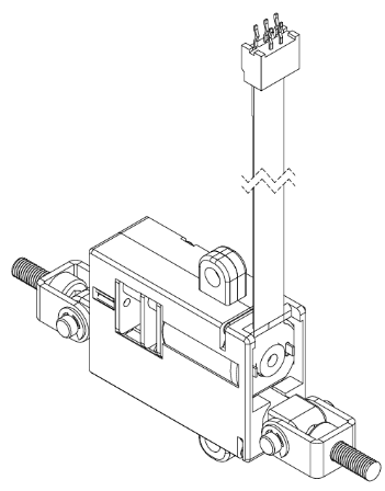
Nano Series Limit Switch Datasheet
Features
- Nano size linear actuator with 15mm stroke length
- Integrated DC motor, gear box, leadscrew and built-in limit switches
- Extends when constant voltage is applied, and retracts when reverse voltage is applied
- Immediate operation with simple control and installation (no communication control required)
- 7N and 12N rated load models depending on lead screw specifications
- Stroke can be adjusted using a separately applied micro switch
Specification
Model | 12D-7S-15 | 12D-12S-15 |
|---|---|---|
Stroke | 15mm (± 1mm) | |
Limit Switch | Yes (Built-in) | |
Repeatability | ±0.5mm | |
Rated Load | 7N (0.71 kgf / 1.57 lbf) | 12N (1.22 kgf / 2.69 lbf) |
Max Applicable Load | 14N (1.42 kgf / 3.14 lbf) | 24N (2.44 kgf / 5.38 lbf) |
Recommended Duty Cycle | 20% | |
Rated Voltage / Input Voltage | 12VDC / 7 ~ 13VDC | |
Motor Type | Brushed Cored DC Motor | |
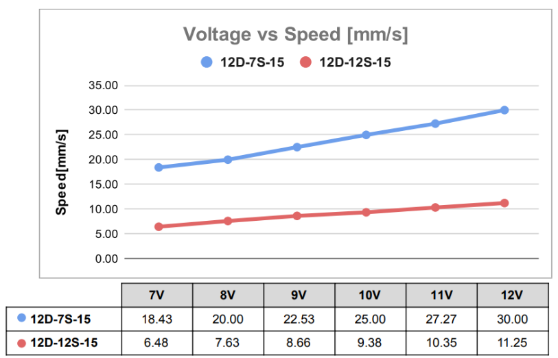
Max Speed (at No Load) | 30mm/s | 11.25mm/s |
Current Consumption | 0mA(Idle), 20mA(No Load), 40mA(Rated), 200mA(Stall) | |
Operating Temperatures | -10 ℃ ~ 60 ℃ | |
Ingress Protection | IP-54 | |
Gear Ratio, Lead Screw | 30:1 / Triple-start screw | 30:1 / Single-start screw |
Mechanical Self-Lock | N/A | Available |
Dimension / Weight | 32.0(L) 21.5(W) 12.0(H) mm / 17g | |
Mechanical Backlash | 0.4mm | |
Cable | Flexible PCB 5P | |
Connector | 1.00mm Pitch FPCB Connector | |
Standard Accessory | 1. 2 x U-Type Bracket | |
Figure 1. Voltage/Speed[mm/s]
 ### Figure 2. Voltage / Stall Force[N]
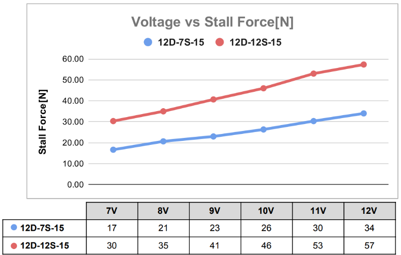
Stall force is for reference only. In order to prevent the damage of product, please use it according to the Rated load when using in actual application
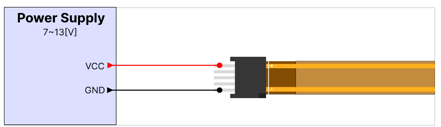
Figure 3. Basic connection
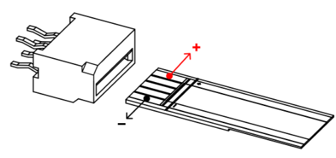
Connect the FPCB and connector in the correct direction as shown in the image above. If connected incorrectly, the actuator will not operate.**
Connection for Forward rotation
Connection for Reverse rotation
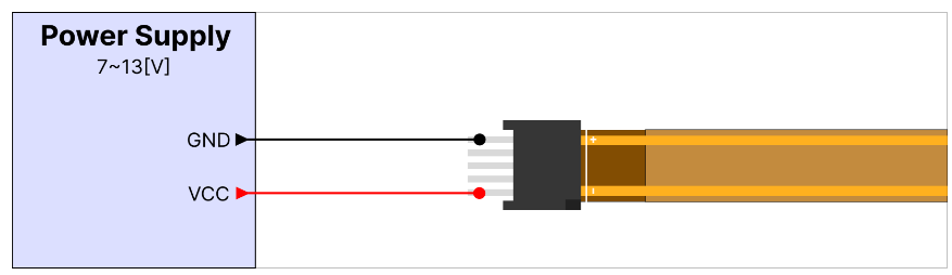 - Connect as shown in the wiring diagram above using the FPCB connector included in the package.
Control the direction by applying positive/reverse voltage to the actuator’s flexible PCB.
Use the optional DPDT switch for easier change of the operating direction.
The voltage application range is 7V ~ 13VDC, but the power will be weak and the speed will be slow at voltages below 12V as 12V is the rated voltage.
Since the motor can be damaged if higher voltage than 13V is applied, make sure to apply a voltage of 12V or lower.
Figure 3.1 DPDT Switch Connection (DPDT Switch sold separately)
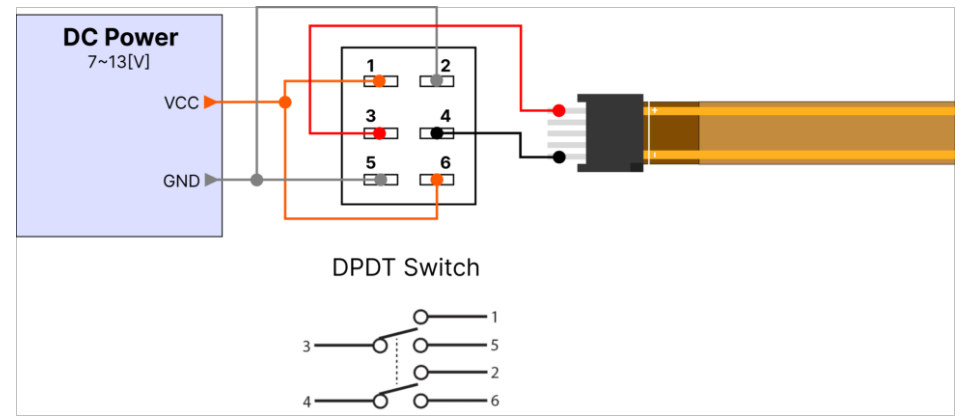 - The DPDT switch (sold separately) has two built-in SPDT switches and performs the same operation.
The switch operation according to the above wiring diagram is as shown in the table below.
Be careful with wiring to avoid short circuits due to incorrect wiring. DPDT switch pins must not come into contact with each other)

Figure 3.2 DPDT Relay Connection
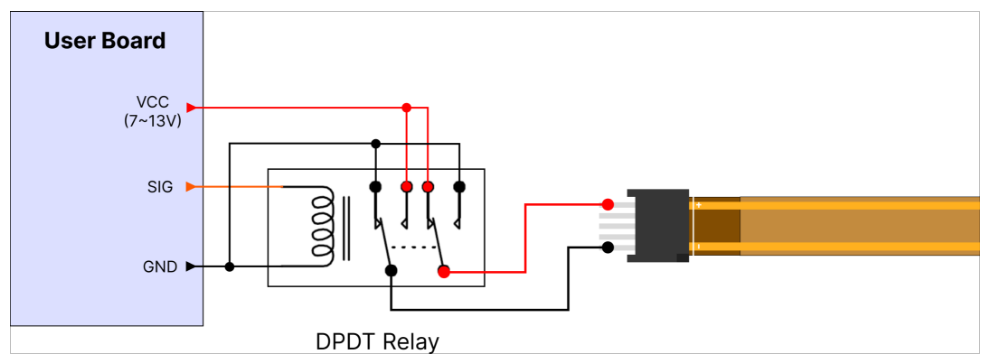 - Can be used to control the forward/reverse direction electrically rather than with a physical switch.
- In addition to the actuator power, a signal voltage is required to control the relay. (According to the relay specifications)
- The switch operation according to the above wiring diagram is as shown in the table below.
- Be careful with wiring to avoid short circuits due to incorrect wiring. (DPDT switch pins must not come into contact with each other)
SIG | RED(+) | BLACK(-) | Operation |
L | VCC | GND | CW |
H | GND | VCC | CCW |
Figure 3.3 Micro Limit Switch Connection
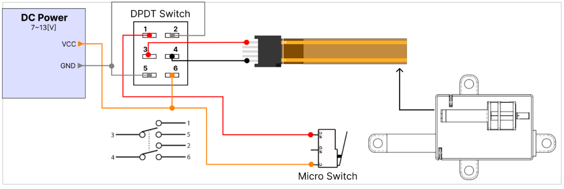 - To implement a shorter stroke than the standard 15mm stroke, install an additional Micro Limit Switch externally, and then wire it according to the DPDT switch wiring diagram above.
- When the actuator rod presses the externally installed Micro Switch, the operation stops.
- Be careful with wiring to avoid short circuits due to incorrect wiring. (DPDT switch pins must not come into contact with each other)
DPDT Switch | Micro Switch | N.O | N.C | RED(3) | BLACK(4) | Operation |
▲ | OPEN (Not pressed) | X | COM | VCC | GND | CW |
CLOSE (Pressed) | COM | X | X | GND | STOP | |
▼ | OPEN (Not pressed) | X | COM | GND | VCC | CCW |
Figure 4. How to use Accessory
Before assembling accessories)
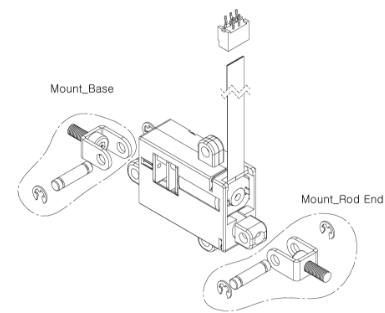
After assembling accessories