IR-UART01 Datasheet
(UART to Half Duplex TTL / RS485 Converter)
Introduction
The IR-UART01 is a UART to Half Duplex TTL (or RS-485) converter that can control the mightyZAP linear actuator through Half Duplex TTL or RS-485 communication using UART signals in an embedded (user board) environment.
DC 3.3V for communication and motor input power must be applied separately through the power terminal according to the input voltage of the purchased mightyZAP actuator.
Various parameter settings, operation tests are available according to the Command Packet. Please refer to the actuator user manual for more detailed info.
1. Features
- Product Category : UART to Half Duplex TTL/RS485 Converter
- Compatible System : Embedded, Arduino, Raspberry PI, etc.
- Baudrate : 9600 ~ 115200 bps
- Logic Input Voltage : 3.3V
- Actuator Supply Voltage : DC 7⁓27V
- Current Capacity : 4A (Max)
- RS485, TTL ESD Protection
- Optional Terminating Resistor
- Storage temperature : -40℃ ~ 105℃
- Operating temperature : -40℃ ~ 85℃
- Size : 42 x 24 x 24.6 mm (With Support)
- Weight : 7.3g
2. PIN Map
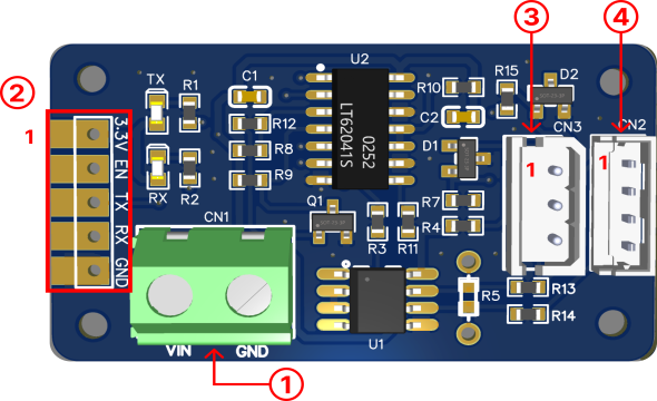
1) Actuator Power Input
| PIN NUMBER | PIN NAME | FUNCTION |
|---|---|---|
| 1 | VIN | Actuator Power Input |
| 2 | GND | GND |
**CAUTION**
Proper input voltage(12 or 24V) must be supplied according to the input voltage specification of your mightyZAP actuator.
2) Signal Pin
| PIN NUMBER | PIN NAME | FUNCTION |
|---|---|---|
| 1 | 3.3V | Supply Voltage |
| 2 | EN | Driver Enable |
| 3 | TX | Transmit Data |
| 4 | RX | Receive Data |
| 5 | GND | GND |
3) TTL Port
| PIN NUMBER | PIN NAME | FUNCTION |
|---|---|---|
| 1(BLACK) | GND | GND |
| 2(RED) | VCC | Actuator Power Input |
| 3(WHITE) | SIG | DATA |
4) RS485 Port
| PIN NUMBER | PIN NAME | FUNCTION |
|---|---|---|
| 1(YELLOW) | D- | RS-485- |
| 2(WHITE) | D+ | RS-485+ |
| 3(RED) | VCC | Actuator Power Input |
| 4(BLACK) | GND | GND |
CAUTION
Be careful of miswiring and short circuits to prevent damage of the board or actuator. We recommend using a genuine wire harness or bulk connectors from us.
3. ELECTRICAL CHARACTERISTICS
- TTL / RS485 Converter Supply
| Parameter | Symbol | Min | Typ | Max | Unit | Remarks |
|---|---|---|---|---|---|---|
| Supply Voltage | 3.3V | -0.3 | 3.3 | 4.6 | V | TTL, RS485 VCC |
| Enable Input Voltage | EN | -0.3 | - | 7 | V | Output Enable Pin H(> 2V) : Transmit L (< 0.8V) : Receive |
| Data Input Voltage | Tx | -0.3 | - | 7 | V | Transmit Data Input |
| Data Output Voltage | Rx | -0.3 | 3.3 | 3.6 | V | Receiver Data Output |
| Communication Current | 3.3V | ≤ 100 | mA | - | ||
| Idle Current | 3.3V | ≤ 10 | mA | - |
- Actuator Supply (Voltage applied solely to the actuator)
| Parameter | Symbol | Min | Typ | Max | Unit | Remarks |
|---|---|---|---|---|---|---|
| Actuator Power Input | VIN | 7.0 | 12.0 | 27.0 | V | Actuator Power Input |
| Current Capacity | VIN | - | - | ≤ 4.0 | A | Actuator Current consumption |
**CAUTION**
The rated input voltage of the L12, 12Lf, and 17Lf series is 12V. Actuator may damage if voltage over 13V is applied.
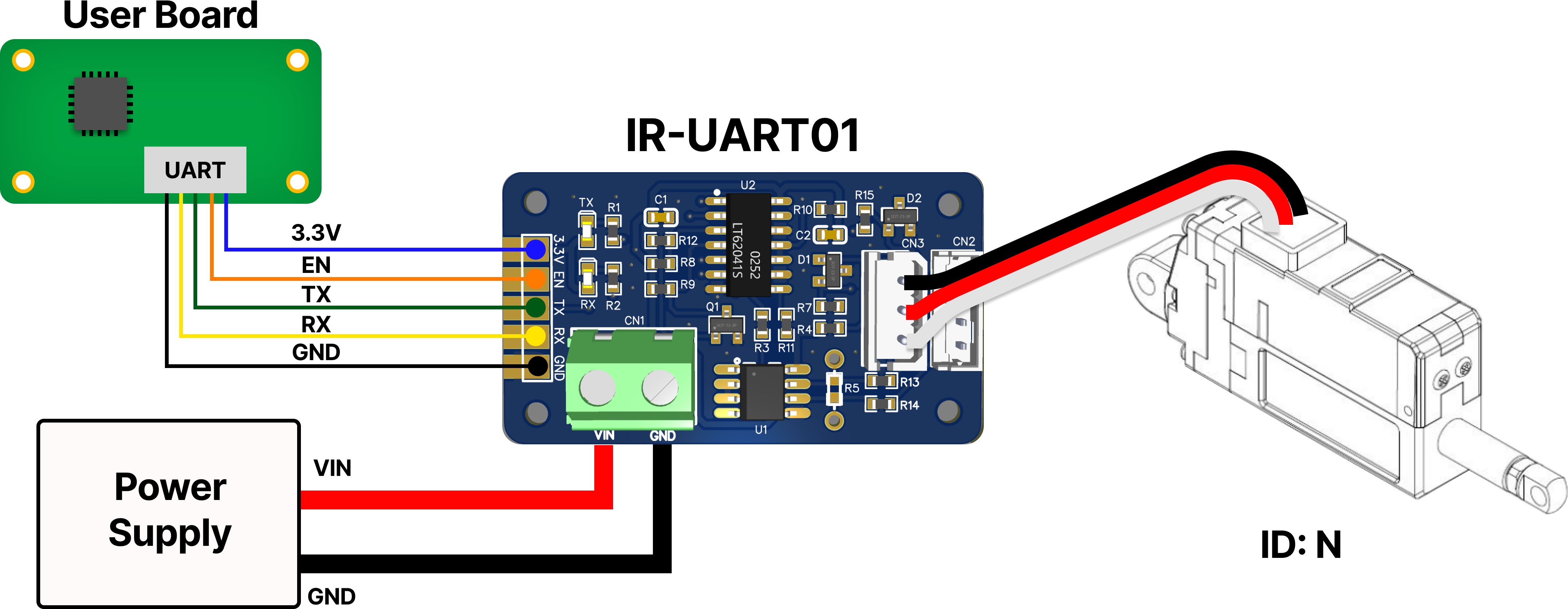
4. Basic Connection
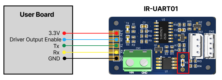
- Refer to the diagram above and connect the pins properly.
- The TX of the User board must be connected to the TX of the IR-UART01. (The RX pins must also be connected to each other.)
- Be careful of miswiring and short circuits. Wiring problems can result in improper operation or damage to the PCB board.
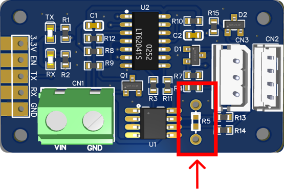
- If a termination resistor is required during RS485 communication due to long wiring lengths or electrical noise environments, solder a 120 ohm resistor to the position marked in red, R5. (120 ohms is typically used, but the resistance value can be adjusted through waveform testing in user condition.)
1) TTL Model
2) RS485 Model
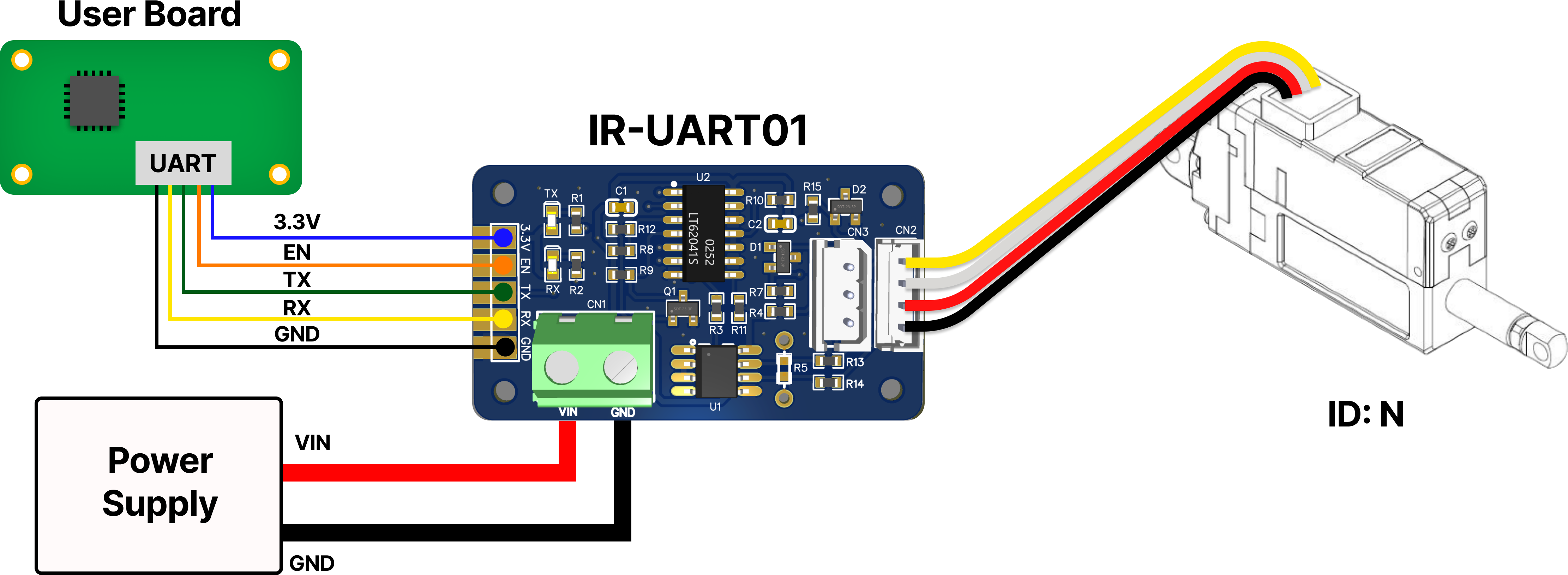
CAUTION
It is not recommended to control TTL and RS485 Model at the same time. 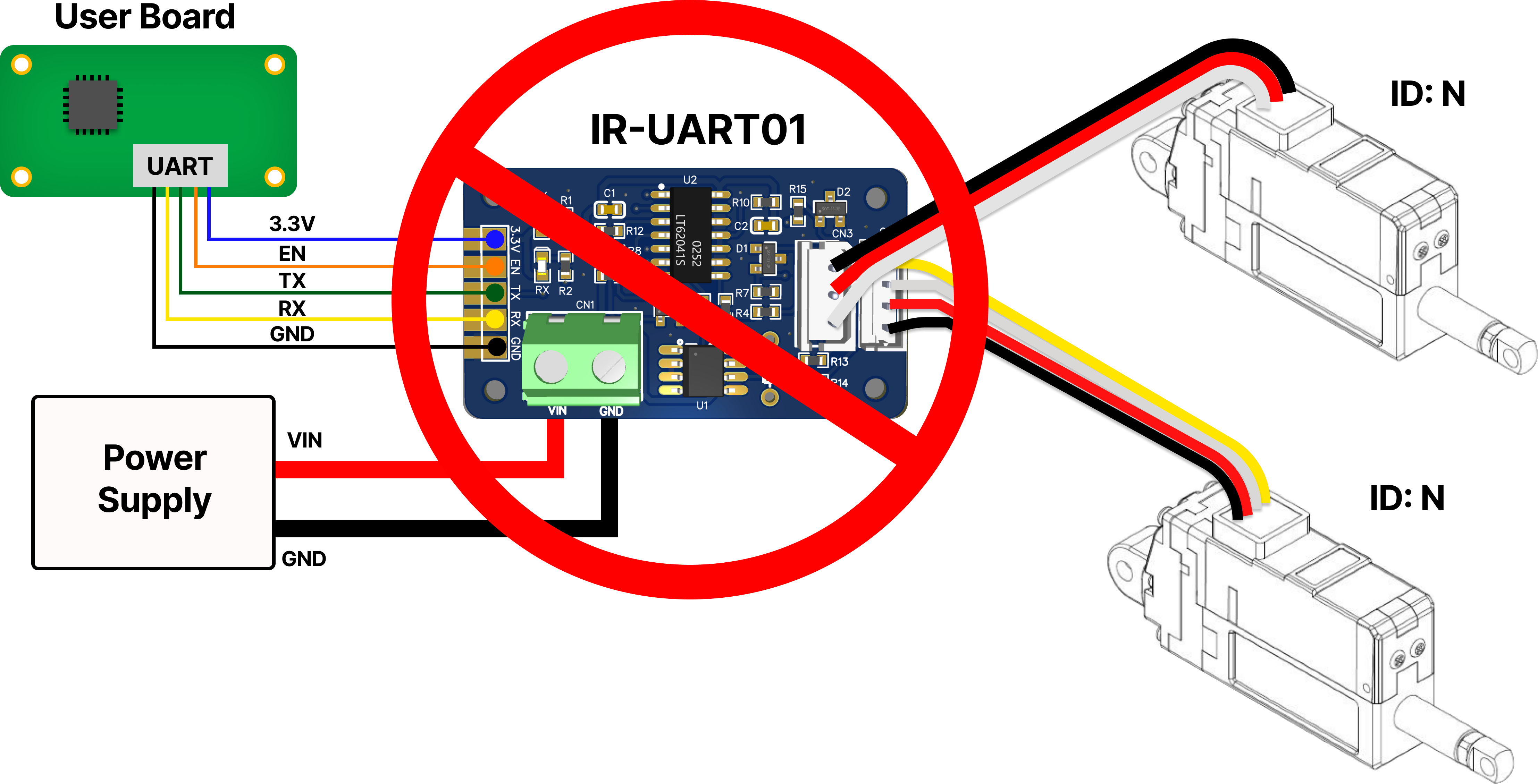
5. Connect multiple actuators
5.1 Daisy-Chain Connection
When transmitting a Command Packet for ID N, only the actuator with ID N among several actuators returns the Feedback Packet and executes the command. 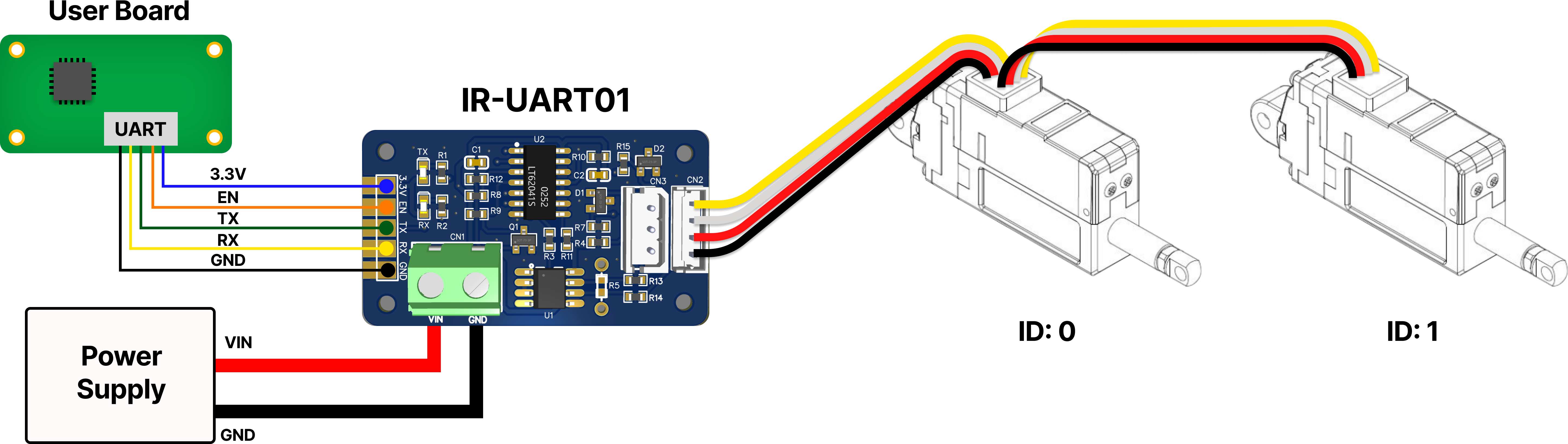
CAUTION
Considering the actuator's default Stall Current (Goal Current 800), it is not recommended to connect more than 4 mightyZAP actuators to IR-UART01 at the same time. If it is used higher than the maximum current value of IR-UART01, there is a risk of PCB damage or fire.
5.2 More Connection
When using more than 4 actuators, supply actuator power separately from outside to ensure product stability. 
6. RS485 Terminating Resistor
Reflected waves may occur depending on the characteristic impedance of the data transmission line. If a termination resistor is needed depending on user’s environment, apply the resistor as described below.
To apply RS485 termination resistance, apply 120Ω resistor to R5 by soldering as shown image. (Generally, 120Ω is used, but the resistance value can be added or subtracted through users waveform testing.)